Srp-270, Rev. 3.02 – BIXOLON IMPACT PRINTER SRP-270 User Manual
Page 60
Rev. 3.02
- 60 -
SRP-270
[ Description of Timing chart.2 ]
When head carriage step motor stops(left →
⑬
left)
The start position of head carriage step motor from right to left
⑭
When fir
⑮
st outing of head pin from right to left
When last outing of head pin from right to left and when starting line feed
ⓐ
When ending of printing from fight to left
ⓑ
The start position of second printing from left to right
ⓒ
Solenoid on time(unlocking colo
ⓓ
r-change printing) : 24ms
When head carriage tip covers the home sensor
ⓔ
(after printing from right to left)
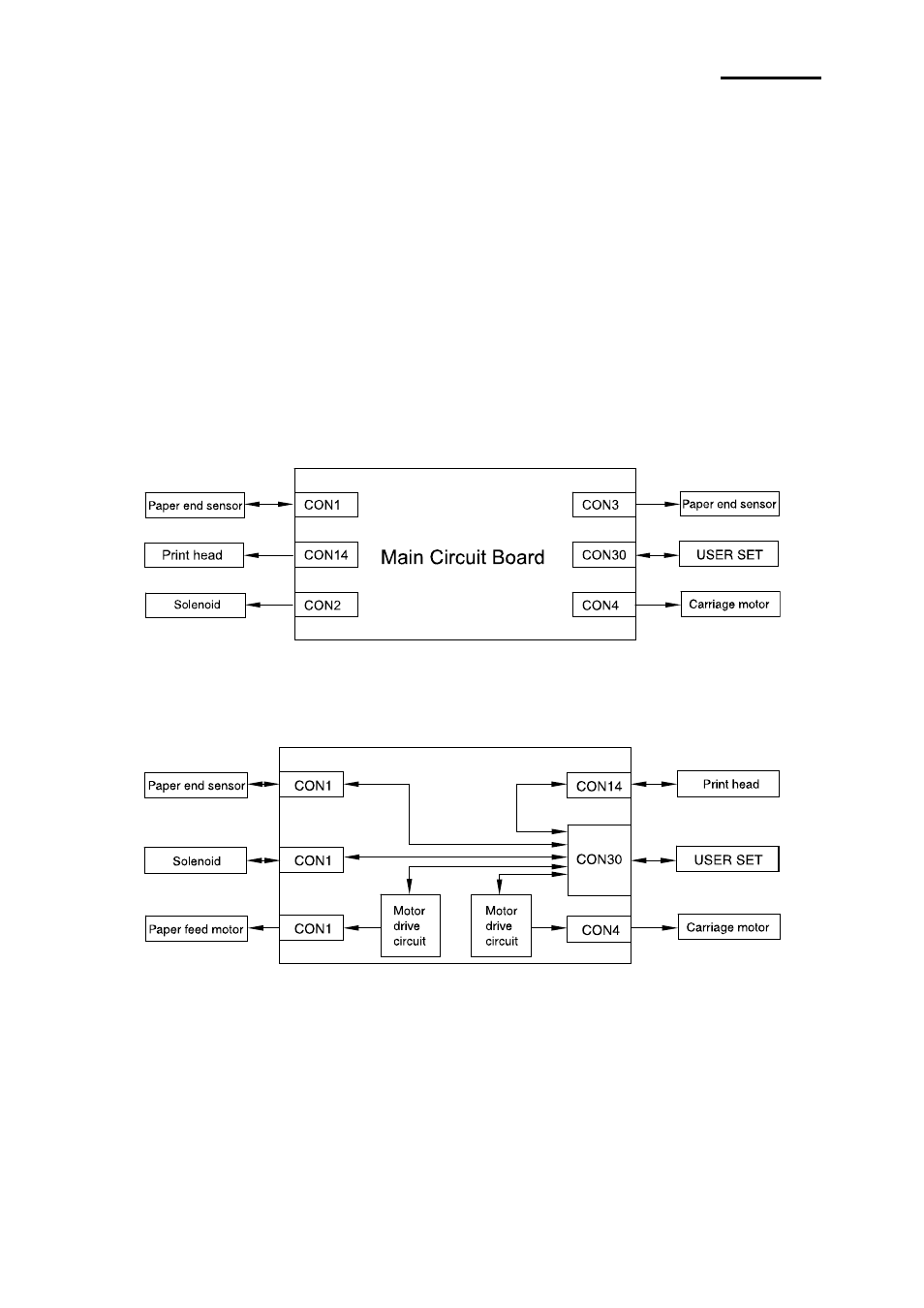
* Electrical Circuit Operation Principles (Hardware Configuration)
[ Component connection diagram ]
The electrical circuitry of the printer consists of the main circuit board and the interface circuit boards.
The figure below is a component connection diagram of the electrical circuitry.
[ Circuit board block diagram ]
The figure below illustrates the circuit block diagram for the printer.