Wolo 4100 The Deputy User Manual
Page 3
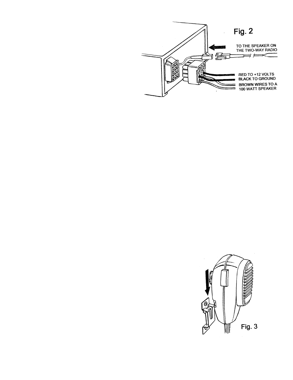
HARNESS WIRE INFORMATION Fig. 2
8. The wire harness provided with the siren has a male
plug end that mates with the connector located in
the back of the siren controller. The plug is designed
to connect and lock only in one position.
WARNING
• Do not connect the wire harness plug to the siren
controller until all connections have been completed,
wires are secured and the installer inspects and
verifies that no short circuits exist.
• Before wiring the siren controller to the vehicle,
carefully review the vehicle’s shop or build manual to ensure the connection points will not affect the circuit or the
vehicle’s operation.
• If the vehicle is equipped with air bags, the installer MUST consult the vehicle’s shop or build manual to ensure that
the siren’s harness wires will not affect deployment of the air bags. If necessary consult manufacturer for their
recommendation.
• Any wires that pass through the vehicle’s firewall or drilled sheet metal must have a rubber grommet or approved
insulator inserted into the hole to protect the wires from being shorted or damaged from rough edges.
• Failure to follow these instructions could cause hazardous sparks, electrical fire, burns and personal injury.
HARNESS WIRING
Speaker: Use 4 to 8 ohm speaker (Not included)
9. BROWN zip cord wires: are connected to speaker. If the harness wires need to be extended, use 18 gauge or
heavier wire.
Radio rebroadcast: Will allow the user to broadcast the vehicle’s two-way radio outside of the vehicle with
controllable volume.
10. WHITE audio wires are connected to the speaker of the two-way radio. If white wires need to be extended, use 18
gauge audio wire or heavier wire.
11. BLACK WIRE is connected to ground. Secure black wire under a metal body bolt in the dashboard area; make
sure that the METAL surface around the bolt is clean of rust and paint to make a good electrical CONNECTION.
12. RED WIRE is connected to the vehicle’s fuse-block or a under dash wire that has 12-volts when the ignition is on.
The red wire is provided with an in-line fuse. (Note: if you need to replace the fuse use a 10 amp.) IMPORTANT:
Carefully review the vehicle’s shop or build manual to ensure the connection points will not affect the circuit or the
vehicle’s operation.
NOTE: Tape all connections and secure wires.
13. Connect the male plug to its female mate in the rear of the siren controller.
Note: The plug is designed to connect and lock only in one position.
MOUNTING MICROPHONE HANGER BRACKET
Fig. 3
Select a location that the microphone can easily be reached. Using the
microphone hanger bracket as a template, mark the two locations and drill to
size, 1/8” drill bit. Secure the microphone bracket with the two-(2) sheet metal
screws provided. CAUTION: Before drilling the surface for mounting of the
microphone bracket, inspect the desired location to ensure that there are no
components, wires and or any other vehicle part that could be damaged by
drilling.
TESTING AFTER INSTALLATION
GAIN CONTROL: The GAIN CONTROL is used to turn on/off the siren controller and adjust the volume. Turn the
rotary GAIN control clockwise, which will turn on the siren controller. Further clockwise rotation of GAIN control will
increase the volume of all siren sounds, P.A system and radio rebroadcast (if that option is used). The maximum
clockwise position of the GAIN CONTROL is determined by either feedback or squeal being amplified. Adjust the GAIN
CONTROL to be positioned just before feedback occurs or to a sound level that is desired.