From, 4' ii m " est " at – Wolo 418-24 Powerhouse User Manual
Page 2
-
4.
For best performance
mount the compressor
close to the trumpets
.
The compressor
is not
water resistant, it is important
that it be mounted inside the vehicle in an area that is dry
.
5. The compressor
should be mounted vertically, with its air outlet facing down.
6.
Drill a 5/16 inch mounting
hole. Using the hardware shown in Fig.
3,
secure compressor.
CAUTION:
Plastic tubing between compressor
and trumpets
should not have sharp bends or
kinks which might stop or reduce air flow, resulting in reduced sound output
.
Fig. 4.
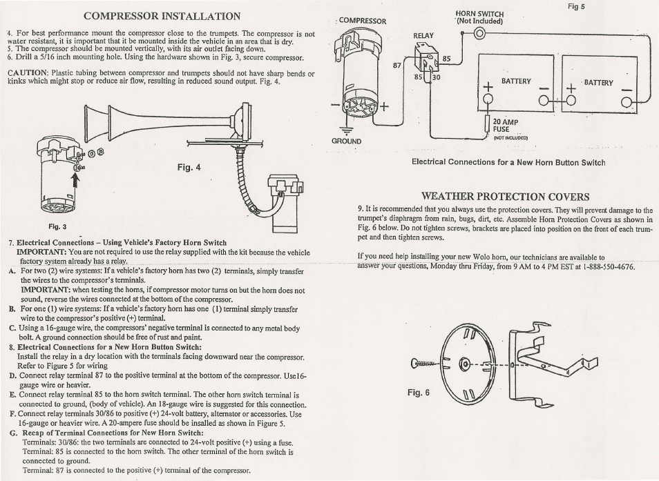
7. Electrical
Connections
- Using Vehicle's Factory
Horn Switch
IMPORTANT:
You are not required to use the relay supplied with the kit because the vehicle
f'!~t<:>!y~y~!e;:
.
~~JI:ell
.
. !J . _ ~ . 5Lr~I{lY. .. . _ ,- " - _ ' _ ' - - - , . -- - - -- - ' . A. For two (2) wire systems: If a vehicle's factory horn has two (2) terminals, simply transfer the wires to the compressor's tenninals. IMPORTANT: when testing the horns, if compressor motor turns on but the horn does not sound, reverse the wires connected at the bottom of the compressor. B. For one (1) wire systems: If a vehicle's factory honi has one (1) terminal simply transfer wire to the compressor's positive (+) terminal . C . Using a I6-gauge wire, the compressors' negative tenninal is connected to any metal body bolt A ground connection should be free of rust and paint 8. Electrical Connections for a New Horn Button Switch: Install the relay in a dry location with the terminals facing downward near the compressor. Refer to Figure 5 for wiring D. Connect relay terminal 87 to the positive terminal at the bottom of the compressor. Use I 6- gauge wire or heavier. E. Connect relay terminal 85 to the horn switch terminal . The other horn switch terminal is connected to ground , (body of vehicle) . An I8-gauge wire is suggested for this connection. F . Connect relay terminals 30/86 to positive (+) 24-volt battery, alternator or accessories. Use I6-gauge or heavier wire . A 20-ampere fuse should be insalled as shown in Figure 5. G. Recap of Terminal Connections for New Horn Switch: Terminals: 30/86: the two terminals are connected to 24-volt positive (+) using a fuse . Tenninal: 8S is connected to the horn switch. The other terminal of the horn switch is connected to ground. Term i nal : 87 is connected to the positive (+) terminal of the compressor . HORN SWITCH . (Not Included) o + BATTERY _ 9. It is recommended that you always use the protection covers. They will prevent damage to the , etc. Assemble Horn Protection Covers as shown in Fig . 6 below. Do not tighten screws, brackets are placed into position on the front of each trum- pet and then tighten screws. If you need help installing your new Wolo horn, . our technicians are available to answer youi ' qiiestions; - Moriday ' fliru " Priday ; from " 9AM " ' to ' 4 ' Ii M " EST " at i ~ 888-550-4676.
trumpet's diaphragm from rain, bugs, dirt