Titus Pneumatic Controls IOM User Manual
Page 6
PNEU-IOM-6.0
5-2-05
Calibration Procedure for TITUS IIA Controller
A.
Direct Acting Cooling or Reverse
Acting Heating.
1.
Adjusting minimum air flow:
a.
Apply zero PSI signal to Port T
on the controller.
b.
If the minimum CFM equals
zero, the damper should
assume a closed position
(observe the indicator on the
end of the damper shaft). If not,
adjust the LO STAT knob on
the controller until the damper
is closed.
c.
If a non-zero minimum CFM is
required, read the differential
pressure for the desired CFM
from the calibration curve
corresponding to the inlet size
of the terminal being calibrate
(Page 8).
d.
Adjust the LO STAT knob until
the desired differential pressure
is read on the manometer
gauge. Allow several seconds
for the controls to react to the
system pressure and stabilize.
2.
Adjusting maximum air flow:
a.
Apply 15-25 PSI signal to
Port T on the controller.
b.
Refer again to the calibration
curve (Page 8).
c.
Adjust the HI STAT knob on
the controller until the
manometer gauge reads the
required differential pressure
from the curve.
NOTE: If actuator fails to respond,
see Guide to Service Procedures.
B.
Reverse Acting Cooling or Direct
Acting Heating
1.
Adjusting maximum air flow:
a.
Apply zero PSI signal to Port T
on the controller.
b.
Refer to the calibration chart
(Page 8). Read the differential
pressure for the desired
maximum CFM from the curve
corresponding to the inlet size
of the terminal being calibrated.
c.
Adjust the LO STAT knob on
the controller until the desired
differential pressure is read on
the manometer gauge. Allow
several seconds for the
controls to react to the system
and stabilize.
2.
Adjusting minimum air flow:
a.
Apply 15-25 PSI signal to
Port T on the controller.
b.
If the minimum CFM equals
zero, the damper should
assume a closed position
(observe indicator on the end
of the damper shaft). If not,
adjust the HI STAT knob until
the damper closes.
c. If a non-zero minimum CFM is
required, read the differential
pressure for the required CFM
from the curve (Page 8).
d.
Adjust the HI STAT knob on the
controller until the manometer
gauge reads the desired
differential pressure from the
curve.
NOTE: If actuator fails to respond,
see Guide to Service Procedures.
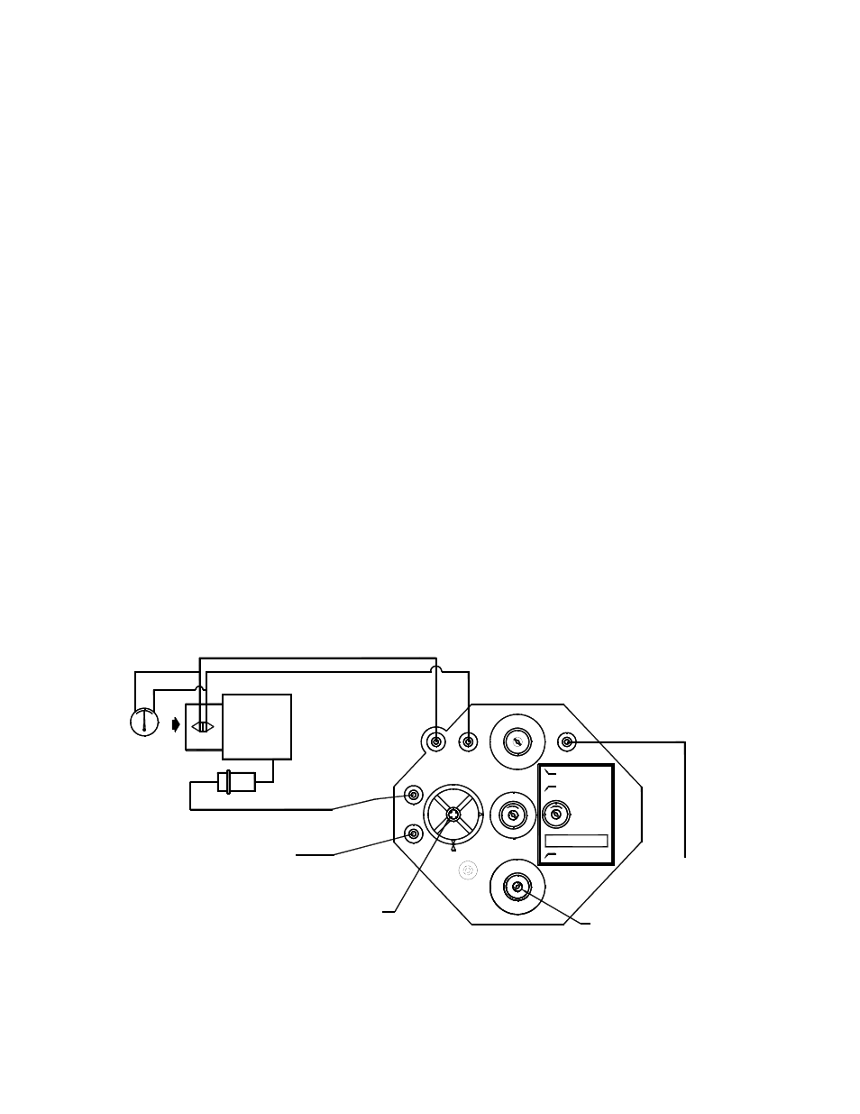
(FIELD ADJUSTERS HAVE KNOBS)
WITH 5/64" HEX ALLEN WRENCH
ALL ADJUSTMENTS CCW TO INCREASE
MAIN AIR (20-25 PSI)
(SUPPLIED IN NO POSITION)
CHANGE DAMPER ACTION
LOOSEN SCREW TO
MAGNAHELIC
SENSOR
(0-20" WG)
GAUGE
ACTUATOR
H
L
HI
LO
NO
DAMPER
BLUE
YELL
OW
M
B
H
GREEN
RED
R
G
N
I
C
NC
L
R
I
RESET SPAN
NC
HI STAT P
RESET START
LO STAT P
T
ROOM THERMOSTAT
(0-15 PSI)
WHITE
Figure 8. Titus IIA Controller