Mab installation manual, Duct insulation and vapor proofing, Sound attenuation – Titus MAB IOM User Manual
Page 5: Condensate drain, Water piping
MAB Installation Manual
IOM-MAB-00
08-15-04
5 of 9
DANGER
BEFORE INSTALLING UNIT, DETERMINE IF THE UNIT
WEIGHT CAN BE SAFELY SUPPORTED.
POSSIBLE INJURY AND DAMAGE MAY RESULT DUE
TO JOIST/TRUSS OVERLOADING.
1. When return air duct connection is smaller than return
air inlet opening, construct the transition piece so the
horizontal and vertical dimensions of transition does
not increase more than one inch for every seven feet
of length.
2. Allow a minimum of three feet of straight ductwork
following an equipment outlet.
3. Install unit with 1/8-inch pitch toward condensate
drain opening.
Duct Insulation and Vapor Proofing
Previously installed heating supply ductwork may already
have adequate insulation against excessive heat loss.
This insulation may be satisfactory for protection against
heat gain from summer cooling. Depending upon
application, additional insulation may be required.
Externally insulated ductwork must have adequate vapor
seal for summer operation, especially where duct is
exposed to high humidity conditions.
Sound Attenuation
Flexible duct connections should be used between the unit
and both the supply and return ducts.
Both suspended and base-mounted units require unit
vibration isolation.
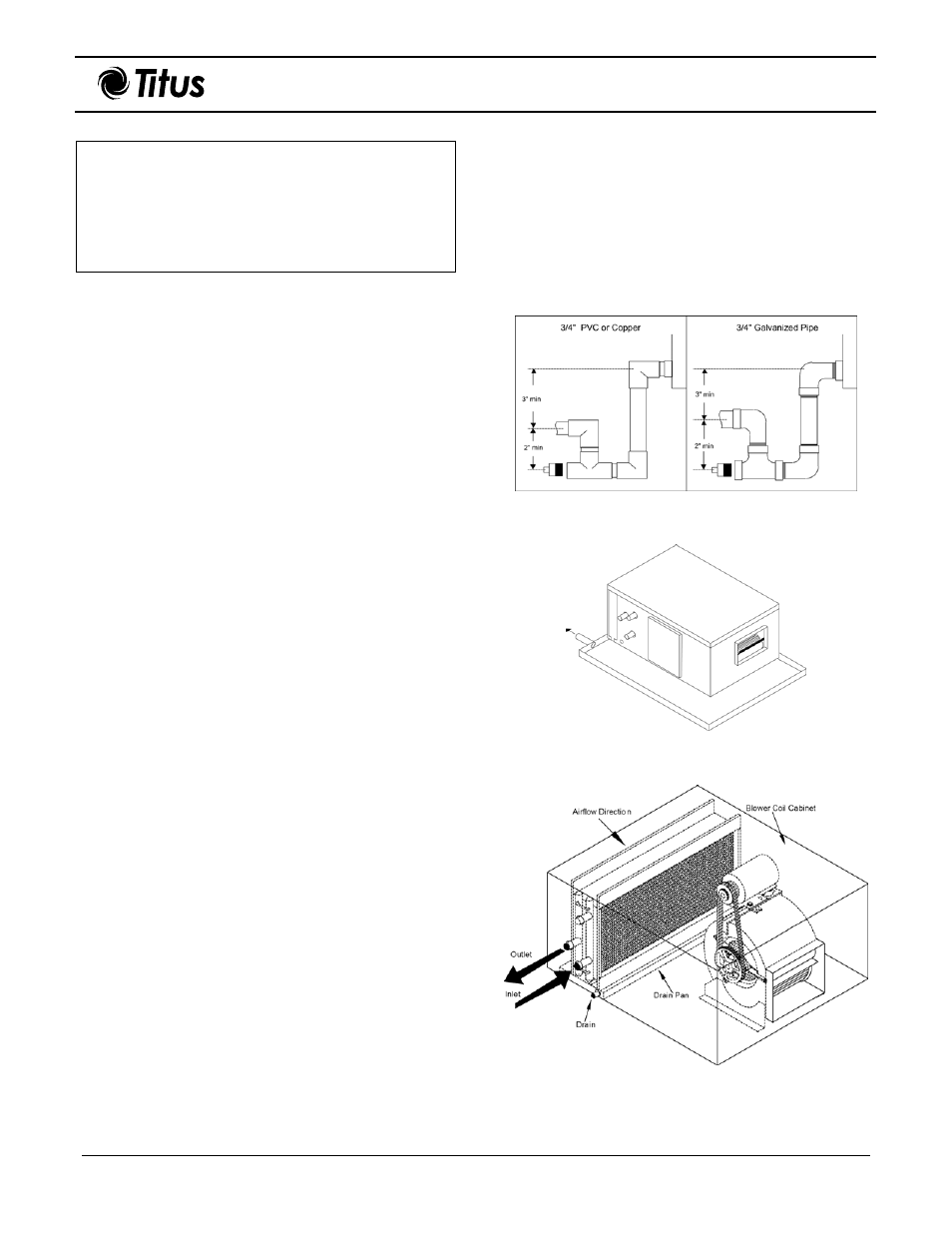
Condensate Drain
Condensate drain must consist of a minimum of ¾-inch
copper tubing, ¾-inch galvanized pipe, or ¾-inch PVC
pipe. Figure 4 shows condensate drain setup. The drain
trap must be properly configured to ensure the removal of
all condensate runoff. Ensure drain pitches downward at a
slope of one inch every 10 feet.
Note 1: Incorrect trapping can hold water in pan,
causing overflow.
Note 2: Consult local codes for additional precautions
before installing condensate pan.
Caution: If unit location is above an occupied
space or where damage may result from
condensate overflow, install a watertight pan
of corrosion-resistant metal beneath unit to
catch overflow. If this condition exists a
separate ¾-inch condensate drain must be
provided for this added pan. See Figure 5.
Water Piping
All piping must be supported, independent of coils. Swing
joints or flexible fittings must be provided to absorb
expansion and contraction strains. Rigid piping reduces
the effectiveness of vibration isolators. The water supply
should always be connected so the entering water is on
the leaving airside of the coil. See Figure 6. Coils must be
adequately vented in order to prevent air binding.
Note: Freeze-ups due to low air temperatures are not
covered under the warranty agreement.
Figure 4. Condensate Drain
Figure 5. Occupied Space Condensate Pan
Installation
Figure 6. Blower Coil Connections