Standard installation, Ductwork, Hab installation manual – Titus HAB Horizontal Air Handler Belt Drive User Manual
Page 3
HAB Installation Manual
IOM-HAB-00
06-30-04
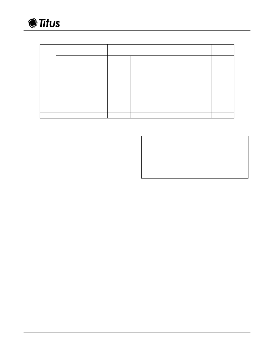
Table 2. HAB Installation Data
4-Row Unit
6-Row Unit
2-Row Coil
1-Row Coil
(Note)
Model Connection
Size OD
SWT
Ship Weight
(lbs)
Connection
Size OD
SWT
Ship Weight
(lbs)
Connection
Size OD
SWT
Ship Weight
(lbs)
Connection
Size OD
SWT
HAB08
3/4"
145
3/4"
156
5/8"
13
5/8"
HAB12
3/4"
171
7/8"
190
7/8"
18
5/8"
HAB16
7/8"
200
1-1/8"
222
7/8"
25
7/8"
HAB20
1-1/8"
244
1-1/8"
263
1-1/8"
30
7/8"
HAB30
1-1/8"
457
1-3/8"
475
1-1/8"
41
N/A
HAB40
1-3/8"
512
1-5/8"
547
1-1/8"
53
N/A
HAB60
1-3/8"
700
1-5/8"
787
1-3/8"
86
N/A
HAB80 (2) 1-5/8"
775
(2) 1-5/8"
855
(2) 1-1/8"
106
N/A
Note: Shipping weight of a one-row coil is same as two-row coils.
Standard Installation
Basic installation procedure covers verifying and/or
installing the following items.
•
Ductwork.
•
Duct insulation and vapor proofing.
•
Unit placement.
•
Sound attenuation.
•
Condensate drain.
•
Water piping.
•
Motors and drives.
•
Electrical connections.
Note: If mixing boxes form part of the unit, install the
mixing boxes prior to installing unit. See Mixing Box
Installation topic within this document.
Ductwork
Use accepted industry practices and design guidelines of
the ASHRAE Fundamentals Handbook. Ductwork must
comply with all building codes and the National Fire
Protection Association’s pamphlet 90A and 90B.
Carefully inspect any previously installed ductwork to
determine suitability.
Note: Ductwork should be of a size meeting
requirements of the installation. Ductwork should
transition gradually from a smaller size blower
outlet to required duct run size to avoid excessive
loss of air velocity.
DANGER
BEFORE INSTALLING UNIT, DETERMINE WHETHER
THE UNIT WEIGHT CAN BE SUPPORTED SAFELY.
POSSIBLE INJURY AND DAMAGE MAY RESULT DUE
TO JOIST/TRUSS OVERLOADING.
When return air duct connection is smaller than return
inlet opening, construct the transition piece so the vertical
and horizontal dimensions of transition do not increase
more than one inch for every seven inches of length.
Allow a minimum of three feet of straight ductwork
following an equipment outlet.
Suspend unit or support unit from floor. Models HAB08
through 20 have 3/8-inch weld nuts provided in each
corner of the top for suspending the unit with threaded
rod. See Figure 3. Models HAB30 through 80 have 7/8-
inch knockouts in each corner of top and bottom panels
for suspension rods to pass through, located 3-1/2 inches
in from corners on centerline. It is recommended that
angle iron or unistrut be used under the unit for support
(these support pieces should extend approximately one
inch beyond each end of the unit, see Figure 4.
Ensure the suspension rods are located so the rods do
not block access panels or interfere with electrical,
mechanical or drain functions of the unit.
Install unit with 1/8-inch pitch toward condensate drain
opening.
3 of 9