Installation, Locating your gas stove, Manufactured mobile home additional requirements – Regency Hampton H15 Small Gas Stove User Manual
Page 9: Combustion and ventilation air, Clearances to combustibles
Hampton® H15-1 Direct Vent Freestanding Gas Stove
9
INSTALLATION
LOCATING YOUR
GAS STOVE
When selecting a location for your stove, ensure
that the clearances listed above are met as well
as ensuring that there is adequate accessibility for
servicing and proper operation.
MANUFACTURED MOBILE
HOME ADDITIONAL
REQUIREMENTS
1) Ensure that structural members are not cut or
weakened during installation.
2) Ensure proper grounding using the #8 ground
lug provided.
3) Appliance must be anchored to the fl oor with
the supplied anchoring methods.
COMBUSTION AND
VENTILATION AIR
The combustion air from this appliance is drawn
from outside the building through the outer fl ue.
Extra provision for combustion air inside the
room is not required.
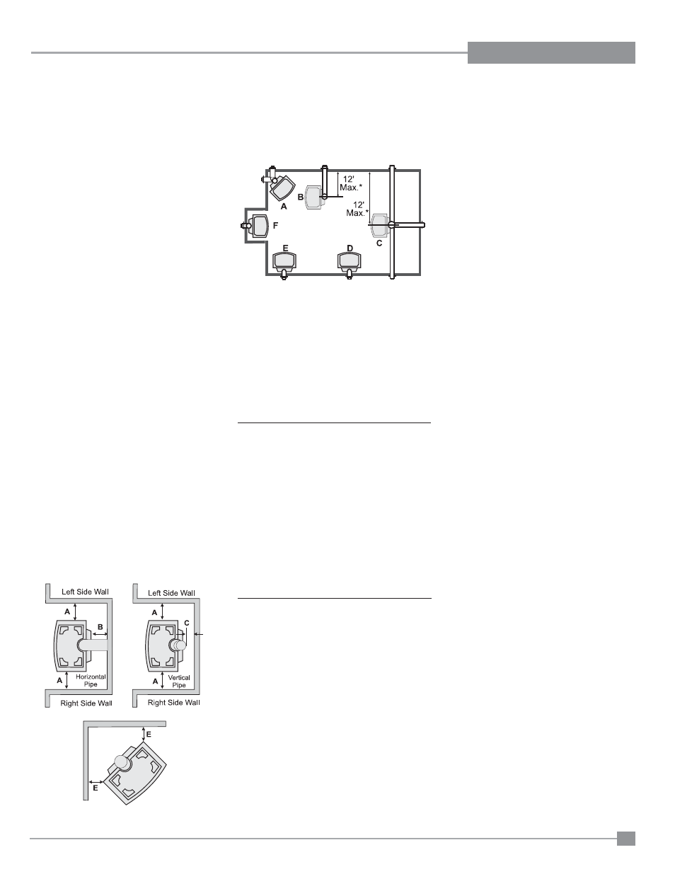
A) Cross
Corner
B) Room
Divider
C) Island
D) Flat on Wall
E)
Flat on Wall Corner
F)
Flush with Wall/Alcove
For Vent Termination requirements, see the "Exterior
Vent Terminal Locations" section.
* 12' max. only if vertical height is achieved.
CLEARANCES TO
COMBUSTIBLES
The clearances listed are MINIMUM distances.
Measure the clearance to both the appliance and
the chimney connector. The farthest distance is
correct if the two clearances do not coincide.
For example, if the appliance is set as indicated in
one of the fi gures but the connector is too close,
move the stove until the correct clearance to the
connector is obtained.
This appliance may be installed only with the
clearances as shown in the situations pictured.
Do not combine clearances from one type of
installation with another in order to achieve
closer clearances.
This unit can be installed on a solid combustible
surface like a wood fl oor. This unit can also be
installed directly on carpeting or vinyl.
Use the minimum clearances shown in the dia-
grams below:
H15-NG1 & H15-LP1 Clearances
A Left Side Wall to Unit*
6" / 150 mm
*B Back Wall to Unit
0" / 0 mm
C Vertical Vent Pipe to Back Wall
2" / 50 mm
E Unit Corner to Wall
2" / 50 mm
Unit Top to Alcove Ceiling 24" / 610 mm
Minimum ceiling height is 24" /610 mm from top
of unit.
*IMPORTANT
It is recommended that unit is moved away from
the wall, if installing the blower option, so the fan
can be easily installed and/or serviced.