Sunnex CS2050D (Dual) User Manual
Page 19
INSTALLATION AND OPERATING MANUAL
18
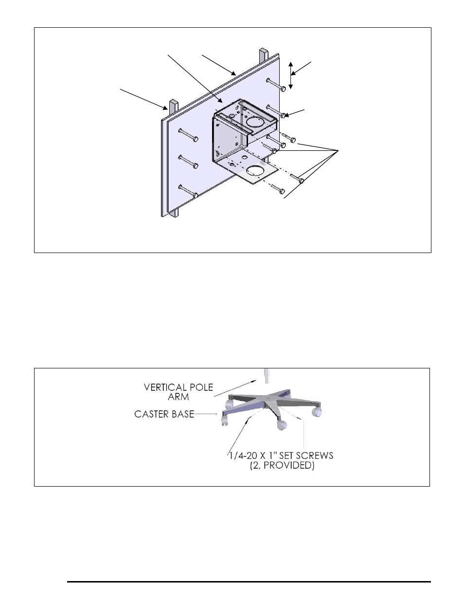
4. Place the wall board in position and secure through the wall to the wooden wall studs, using six
lag bolts. CAUTION! EACH LAG BOLT MUST BE CAPABLE OF RESISTING PULL OUT
AND SHEAR FORCES OF 100 POUNDS (45kg).
5. Ensure the Extension U-arm is level.
6. Follow instructions in section 5.2 (Items 5 thru 9) to complete the balance arm assembly.
5.6 Installation Instructions (Mobile Light)
1. Insert the bottom of the vertical pole arm into the center housing of the caster base. Secure the
vertical pole with the two (2) provided (1/4-20 X 1”) set screws using provided Allen wrench.
Figure 15
2. Follow instructions in section 5.2 (items 5 thru 9) to complete the light assembly.
Edge distance (any edge)
1-1/2” (19mm) minimum
Supplied high
density wall board
1/4” X 5” (M6X13cm) long steel
hex head lag bolts. Minimum 6
required
The bracket is secured to
the wall board. 4 x 3/8”
(M10) bolts.
CAUTION! Do not use lag
bolts if wall studs are metal.
Appropriate fasteners must be
utilized.
Wood or metal stud
Dry wall
Figure 14