Sunnex CS2050D (Dual) User Manual
Page 17
INSTALLATION AND OPERATING MANUAL
16
with each light) can then be used to cover the hole in the drop ceiling created for the
extension arms.
3.
The dimensions and recommended installation heights are identical to the single ceiling arm.
5.4 Installation Instructions (Ceiling Dual Light)
1.
Follow instructions in sections 5.1 and 5.2 to complete installation of lights to ceiling.
Figure 11
2.
If using dual mount seismic bracket, securely fasten dual mount seismic bracket to a
structural member in the ceiling. Three ½" (12mm) holes on a 12" (30.4cm) bolt circle have
been provided on the flat plate of seismic bracket.
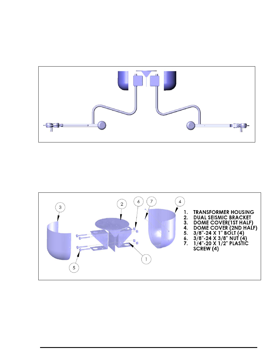
3.
To install dome covers, position both halves of the dome and secure with the 4 plastic screws
provided. (There is a nylon collar on ceiling arm just below the transformer box, adjust the
collar by loosening the set screw on collar so it holds the dome covers).
Figure 12
5.5 Installation Instructions (Wall Light)
1. Locate the two wall studs or other permanent members to which the board is to be affixed.
2. For a room with a floor-to-ceiling distance of eight feet, mark the position of the wall board on
the wall so the bottom of the wall bracket is 64.875” (165cm) from the floor surface. This will
result in floor to light clearance of 75” and should place the Extension U-arm where it will
move freely without scraping the ceiling. (This is based on the assumption that the floor-to-
ceiling height is 8’ (2.4m)).