Schwank ThermoControl Plus Series CM-485 User Manual
Page 7
- 7 -
The answer may be:
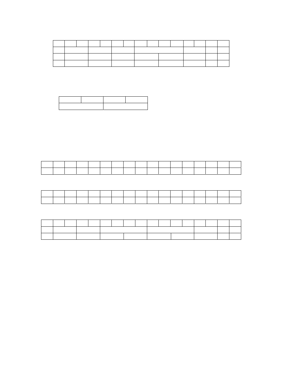
:020302810375
1 2 3 4 5 6 7 8 9 10
11 12 13 14 15
: Dev addr Status
Length
Data
LRC CR LF
:
02 03 02 81 03 75
0Dh
0Ah
Hi
Lo
The “Length” indicates that there will follow 2 byte. The 16-bit figures will arrive in
High-Low order.
Byte order of the 32-bit figures: (sample: 4byte work-hour counter)
Hi Lo Hi Lo 2x16bit
Hi Lo
32bit
Register writing
In this example we are writing “1” to address “2”.
:020600020001F5
1 2 3 4 5 6 7 8 9 10 11 12 13 14 15 16 17
:
0 2 0 6 0 0 0 2 0 0 0 1 F 5
0Dh 0Ah
As an ASCII code:
1 2 3 4 5 6 7 8 9 10 11 12 13 14 15 16 17
3Ah 30h 32h 30h 36h 30h 30h 30h 32h 30h 30h 30h 31h 46h 35h 0Dh 0Ah
Structure:
1 2 3 4 5 6 7 8 9 10 11 12 13 14 15 16 17
: Dev addr fcode
Reg. address
Data
LRC
CR LF
Hi Lo Hi Lo
In the example the "Dev addr" is the unique number of the device.
The fcode=06 indicates the writing request.
The Reg.address gives the 16-bit address.
Data: contains the 16-bit data.
LRC, CR, LF: same as in case of reading.
Only one 16-bit register can be written at a time.
If there was no error, the answer will be the same as the order:
:020600020001F5