Heavy duty plastic lockers – 40000 series, Locker base installation instructions – Salsbury Industries 40000 Series Heavy Duty Plastic Lockers User Manual
Page 2
Heavy Duty Plastic Lockers – 40000 Series
Locker Base Installation Instructions
IMPORTANT: Make sure the base is square and level before anchoring to the floor. The base may be square but
not level, so be sure to check both. Shim under the base if necessary. This will ensure proper locker operation.
NOTE: The base front pieces are precut to length for 1-wide (12”) or 3-wide (36”) lockers, and come with slotted base side pieces. The length of the
base front pieces may be trimmed during installation by cutting to the desired length. DO NOT cut the base side pieces. The side pieces are the
correct length for 18” deep lockers.
Each set of base pieces includes a package of angle brackets to attach the base pieces to the floor, ¼” x 1-3/4” Tapcon screws to fasten the angle
bracket to the floor, and #10 x ½” sheet metal screws to attach the brackets to the base front and side pieces.
1. Plan the locker layout. Measure and mark placement lines on the floor for the locker bases. One or two lockers will require one or two 1-wide
bases. Three or more lockers in a row will require 3-wide bases and perhaps one or two 1-wide bases. As supplied, the bases are 1” wider than the
basic 12” wide locker to accommodate two (2) 1/2” thick side panels. As additional lockers and bases are arranged in a row with a side panel at one
end or both ends, some of the base front piece(s) must be trimmed by 1” or 1/2” to maintain a flush surface alignment between the end panel and the
base side piece. If side panels are not being used, further trimming of the front base pieces may be necessary
2. Position the base side and front pieces per the floor layout. The ends of the base front pieces fit into the slots in the base side pieces. See the
illustration below. Square and level the base front pieces and side pieces using shims as required. If shims are used, place them under the
mounting brackets perpendicular to the bracket.
3. Using the applicable mounting hardware supplied, anchor the base pieces to the floor. Use a 3/16” masonry drill bit for the 1/4” x 1-3/4” Tapcon
screws. Use at least two (2) angle brackets for each front piece or side piece.
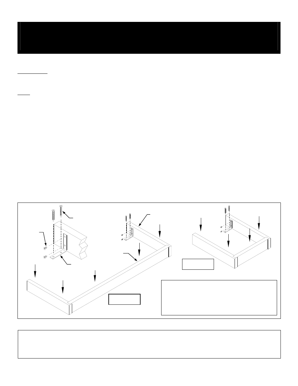
Base Installation
Side Piece
Tapcon Screw
Sheet
Metal
Screws
Angle Bracket
Front Piece
1-Wide Base
Use 1/4” x 1-3/4” Tapcon concrete screws (blue) to attach
angle brackets to floor. Drill pilot hole with 3/16” masonry bit.
Use #10 x ½” sheetmetal screws to attach angle brackets to
plastic base members.
3-Wide Base
SALSBURY INDUSTRIES
1010 East 62
nd
Street, Los Angeles, CA 90001-1598
Phone: 1-800-562-5377 Int’l Phone: 323-846-6700
Fax: 1-800-562-5399 Int’l Fax: 323-846-6800
www.lockers.com engineering
@
lockers.com
Installation instructions are provided as general guidelines. It is advised that a professional installer be consulted. Salsbury Industries assumes no product assembly or installation liability.
Copyright © 2010 Salsbury Industries. All rights reserved. (Rev. 05, 1/13/2010) Page 2 of 6