Salsbury Industries 72000 Series Standard Gear Lockers User Manual
Assembly instructions, Salsbury industries, Typical assembly
SALSBURY INDUSTRIES
1010 East 62
nd
Street, Los Angeles, CA 90001-1598
Phone: 1-800-562-5377 Int’l Phone: 323-846-6700
Fax: 1-800-562-5399 Int’l Fax: 323-846-6800
www.lockers.com engineering
@
lockers.com
Installation instructions are provided as general guidelines. It is advised that a professional installer be consulted. Salsbury Industries assumes no product assembly or installation liability.
Copyright © 2012 Salsbury Industries. All rights reserved. (Rev. 04, 2/10/2012)
Standard Gear Lockers – 71000/72000 Series
Assembly Instructions
Thank you for selecting Salsbury’s standard gear lockers. We are confident that the quality and construction of the lockers will prove to be a good
investment. These instructions are intended to assist you in the assembly and installation of a standard gear locker with locked solid front door,
locked compartment and locked foot locker. Installation hardware is not provided. Individual job conditions will dictate the type of installation
fasteners and whether the lockers must be anchored to the wall, the floor, or both.
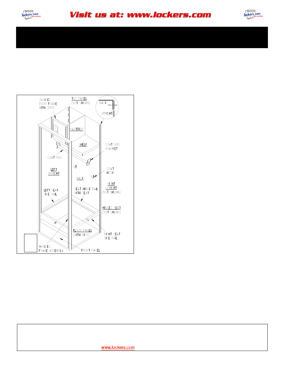
Typical Assembly
Notes
Fasteners are provided to assemble the standard gear locker, but
fasteners are not provided to anchor the locker to the wall, floor, or
another locker. These will vary according to the anchoring
conditions.
All bolted connections should be finger tight initially. Square locker
frame before tightening all connections.
Adjust all doors to operate freely if required. If built-in locks are
installed, make certain locks operate properly before closing doors.
Instructions
1. Assemble left upright to back. Side flange of back should be on
the outside. (Heads of the bolts on the outside with the nuts to
the inside).
2. Add top panel to the back and upright at the top. The top panel
has no stiffening ribs. Top panel flanges should go inside left
upright and back. Rectangular notches go toward the front.
(Heads of the bolts on the outside with the nuts to the inside).
3. Attach 3-sided door frame and door assembly for top
compartment to left upright and top. (Heads of the bolts on the
outside and locker top).
4. Attach partition to back, top panel, and right edge of 3-sided door
frame.
5. Attach shelf underneath the 3-sided door frame to the left upright,
back, and partition.
6. Attach right upright to back, top panel, and shelf.
7. Attach floor panel to back, left upright, and right upright. Floor
panel has 2 stiffening ribs underneath. Rectangular notches go
to the front.
8. Attach left seat side rail to left upright and right seat side rail to
right upright.
9. Attach the hinge rail with seat assembly to the left and right seat
side rails
10. Attach coat hooks, coat rod brackets, and coat rod. (Heads of
the bolts on the outside with the nuts to the inside).
11. Attach front panel to 4-sided frame assembly with front door.
(Heads of the bolts on the inside of the front panel with the nuts
on the inside of the frame).
12. Bolt 4-sided frame assembly with front panel and front door to the
assembled locker body. (Heads of the bolts on the outside with
the nuts to the inside). This completes the assembly of the
standard gear locker.
FRONT
DOOR
NOT
SHOWN