D. digital inputs and sensors – Pololu 3pi Robot User Manual
Page 17
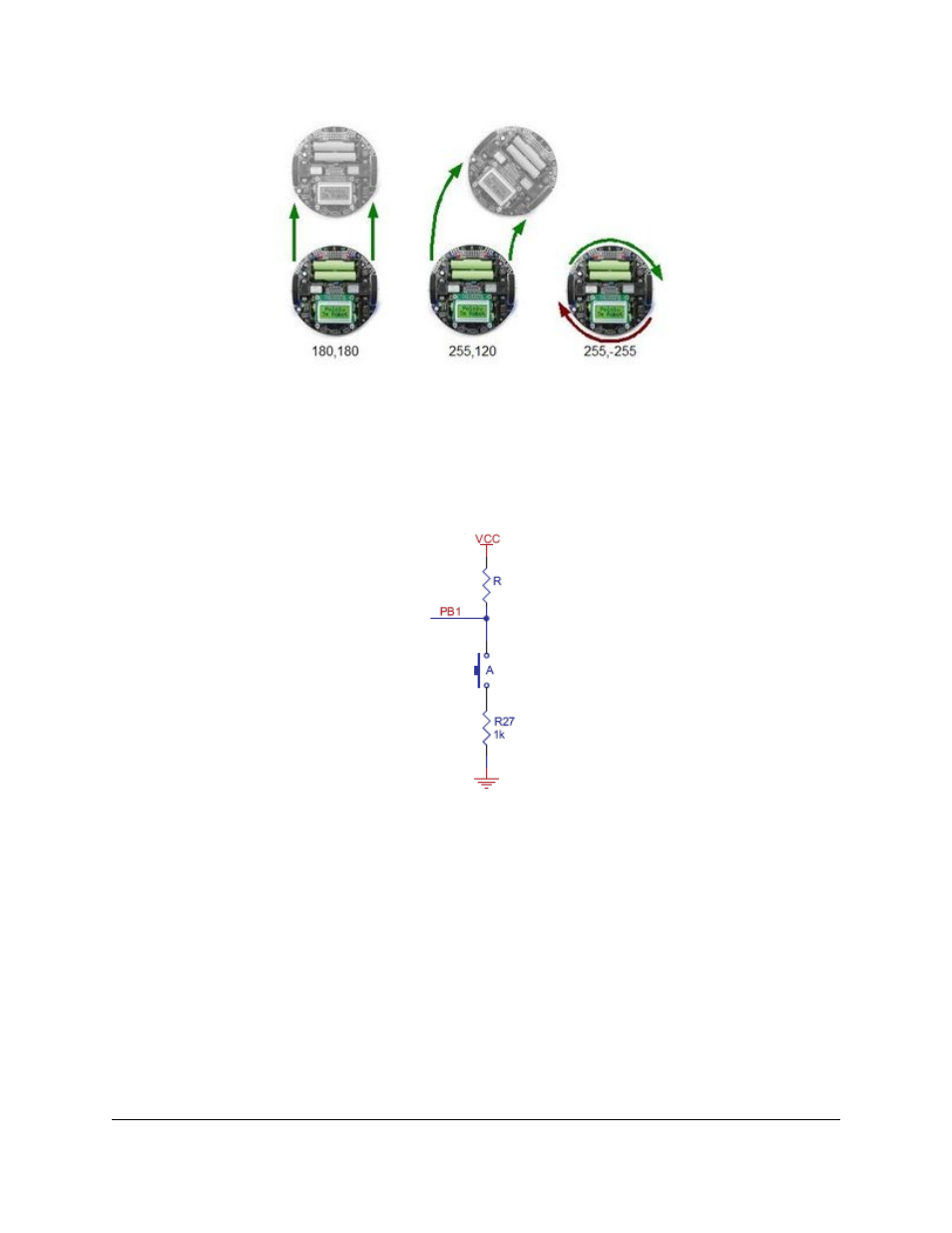
The 3pi demonstrating the effects of various motor
settings.
5.d. Digital inputs and sensors
The microcontroller at the heart of the 3pi, an Atmel AVR mega168 or mega328, has a number of pins which can be
configured as digital inputs: they are read by your program as a 1 or a 0 depending on whether the voltage is high
(above about 3 V) or low (below about 1.5 V). Here is the circuit for one of the pushbutton inputs:
Normally, the pull-up resistor R (20-50 k) brings the voltage on the input pin to 5 V, so it reads as a 1, but pressing the
button connects the input to ground (0 V) through a 1 k resistor, which is much lower than the value of R. This brings
the input voltage very close to 0 V, so the pin reads as a 0. Without the pull-up resistor, the input would be “floating”
when the button is not pressed, and the value read could be affected by residual voltage on the line, interference from
nearby electrical signals, or even distant lightning. Don’t leave an input floating unless you have a good reason. Since
the pull-up resistors are important, they are included within the AVR – the resistor R in the picture represents this
internal pull-up, not a discrete part on the 3pi circuit board.
A more complicated use for the digital inputs is in the reflectance sensors. Here is the circuit for the 3pi’s leftmost
reflectance sensor, which is connected to pin PC0:
Pololu 3pi Robot User's Guide
© 2001–2014 Pololu Corporation
5. How Your 3pi Works
Page 17 of 63