3 configuring the dip-switches, 1 media converter modules - front panel, 2 media converter modules - on-board – Omnitron Systems Technology FlexSwitch 6530 FK User Manual
Page 6: Media converter modules - on-board
3.3
Configuring the DIP-Switches
3.3.1
Media Converter Modules - Front Panel
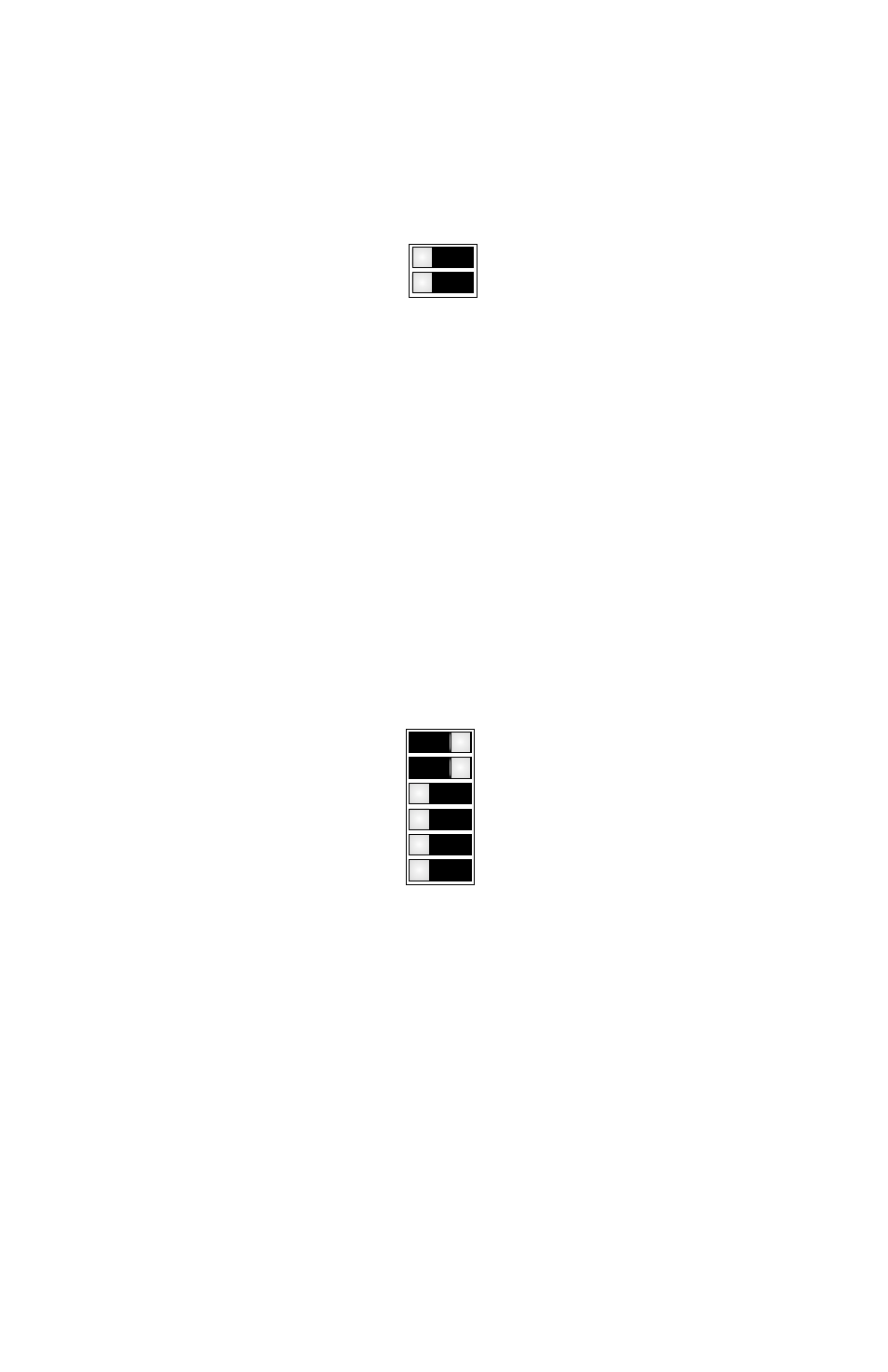
The Media Converter Modules have been pre-configured for full duplex
operation as illustrated below. For half duplex operation, use the front panel
DIP-Switch associated with the appropriate fiber port.
HDX (P1)
HDX (P2)
(P1) FDX
(P2) FDX
Media Converter Module Front Panel DIP-Switches
Fiber Full/Half-Duplex “FDX / HDX” DIP-Switch
When in the Fiber Full/Half-Duplex DIP-Switch is in the “FDX” position
(factory default), the fiber port operates in Full-Duplex mode. When in the
“HDX” position, the fiber port operates in Half-Duplex mode and its distance
is limited by the IEEE 802.3 standard to 412 meters.
3.3.2
Media Converter Modules - On-Board
The Media Converter Modules have on-board DIP-Switches for the
configuration of the Link Modes and Backplane connectivity. See Section 6.0
for more information on the Link Modes. The modules are pre-configured as
illustrated below.
A EN
B EN
LP
RFD
SFD
TEST
(Left Position)
(Right Position)
LS
Media Converter Module On-Board DIP-Switches
A and B Backplane Enable “ A EN, B EN” DIP-Switch
This DIP-Switch must be in the RIGHT position (factory default) for the module
to operate correctly. The backplane must be enabled for the Media Converter
Modules to communicate.
Link Propagate/Link Segment “LP” DIP-Switch
When both the Link Propagate/Link Segment “LP” and the Remote Fault Detect
“RFD” DIP-Switches are in the LEFT position (factory default), Link Segment
mode is enabled. When the Link Propagate/Link Segment “LP” DIP-Switch is
in the Right position, and the Remote Fault Detect “RFD” DIP-Switch is in
Page 6