Omnitron Systems Technology Cable Management Kit for 5-Module Chassis User Manual
Page 2
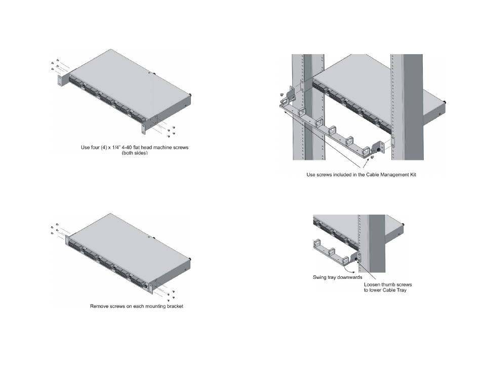
2) INSTALL EXTENDED L-SHAPED MOUNTING BRACKETS
New Installation
Install the extended L-shaped mounting brackets to the sides of the 5-Module chassis as
illustrated in the Figure 1. Use the screws included in the Cable Management Kit.
Figure 1: Installation of Extended Mounting Brackets
After the brackets are secured to the chassis, rack-mount the chassis and Cable Tray to the
equipment rack per Step 3.
Upgraded Installation
On an existing 5-Module chassis with standard mounting brackets, remove and replace the
standard mounting brackets with the extended L-shaped mounting brackets. Remove the four
(4) screws securing the standard mounting bracket to the chassis as illustrated in Figure 2.
Figure 2: Removal of Standard Mounting Brackets
Install the new extended L-shaped mounting bracket as illustrated in Figure 1. Use the screws
included in the Cable Management Kit. After the brackets are secured to the chassis, rack-
mount the chassis and Cable Tray to the equipment rack per Step 3.
Page 3
3) INSTALL CABLE MANAGEMENT TRAY
The Cable Tray and 5-Module Chassis uses the same equipment rack mounting hole. Provide
proper support while mounting the Cable Tray and 5-Module Chassis to the equipment rack.
Secure the Cable Tray and 5-Module Chassis to the equipment rack using the rack mount
screws included in the Cable Management Kit as illustrated in Figure 3.
Figure 3: Cable Tray Installation
4) CABLE MANAGEMENT TRAY OPERATION
Modules can be inserted and/or removed from the chassis by loosening the thumbscrews
and swinging the Cable Tray downwards as illustrated in Figure 4.
Figure 4: Cable Tray Operation
Fiber optic and copper cables are routed through the cable clips on the Cable Tray. Cables
can be routed through both ends of the Cable Tray to maximize the number of installed cables.
A service loop in all cables must be provided to allow the Cable Tray to swing downwards.
Page 2