4 installation, Installation, Elements at the front of the communication module – Lenze EMF2179IB User Manual
Page 36: Emf2179ib communication module (devicenet)
EMF2179IB communication module (DeviceNet)
Installation
Elements at the front of the communication module
5
5.4
5.4.1
5.4-1
EDSDEN EN 02/2006
5.4
Installation
5.4.1
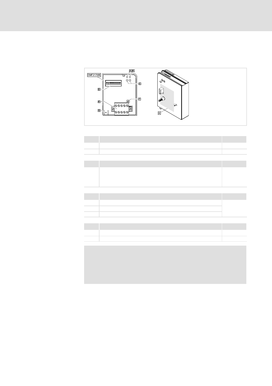
Elements at the front of the communication module
2179DEN001B
Fig. 5.4-1
EMF2179IB communication module (DeviceNet)
Pos.
Description
Notes
Plug connector with double screw connection, 5-pole
5.4-11
PE shield cable connection
Pos.
Description
Notes
DIP switches for setting
z
controller address (S1 - S6)
z
baud rate (S7, S8)
z
software compatibility with 2175 communication module (S10)
5.5-2
Pos.
Description
Notes
Connection status to the drive controller (two-coloured LED)
5.5-11
Connection status to the bus (two-coloured LED)
Drive (green and red drive LED)
Pos.
Description
Notes
Fixing screw
Nameplate
RKOJN
Note!
Only for 820X and 821X:
If required, use an additional PE shield cable which avoids
EMC-related communication interference in surroundings with
extreme disturbances.
Connections
DIP switch
Displays
Other elements