2 basic wiring of profibus, Basic wiring of profibus, Control technology | profibus communication manual – Lenze PROFIBU PC-based Automation User Manual
Page 17: 12 3 r s s r
DMS 2.2 EN 07/2011 TD17
L
17
Control technology | PROFIBUS communication manual
The Lenze control system with PROFIBUS
Brief description of PROFIBUS
4.1.2
Basic wiring of PROFIBUS
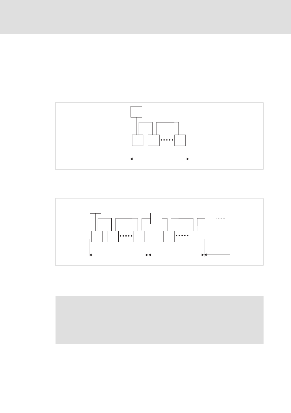
The following examples show two simple PROFIBUS networks.
Each segment of the network must be terminated at both ends. The bus terminators of
PROFIBUS are marked with a "Z" in each of the following examples.
In a PROFIBUS network of only one segment, the PROFIBUS master (M) with an integrated
bus terminator starts the segment, and the connector of the last device (S) with the bus
terminator ends it.
[4-1]
PROFIBUS network with one segment
A PROFIBUS network consisting of several segments contains repeaters (R) for connecting
the segments. The repeaters are provided with integrated bus terminators.
[4-2]
PROFIBUS network with repeater
If no repeater is used at the end of the segment, the bus terminator in the plug of the last
device must be activated.
E94YCPM012a
M
Z
Z
S
S
S
1
E94YCPM012b
M
Z
Z
S
S
S
Z
Z
Z
Z
1
2
3
R
S
S
R
Note!
Repeaters do not have a station address. When calculating the maximum number
of stations, they reduce the number of stations by 1 on each side of the segment.
Repeaters can be used to build up line and tree topologies. The maximum total bus
system expansion depends on the baud rate used and the number of repeaters.