Measuring circuit monitoring output – JUMO 707050 dTRANS T05 - Programmable 2-Wire Transmitter Data Sheet User Manual
Page 4
2012-06-04/00576949
Data Sheet 707050
Page 4/12
JUMO GmbH & Co. KG
Delivery address: Mackenrodtstraße 14
36039 Fulda, Germany
Postal address:
36035 Fulda, Germany
Phone:
+49 661 6003-0
Fax:
+49 661 6003-607
E-mail:
Internet:
www.jumo.net
JUMO Instrument Co. Ltd.
JUMO House
Temple Bank, Riverway
Harlow, Essex CM20 2DY, UK
Phone: +44 1279 635533
Fax:
+44 1279 635262
E-mail:
Internet: www.jumo.co.uk
JUMO Process Control, Inc.
8 Technology Boulevard
Canastota, NY 13032, USA
Phone: 315-697-5866
1-800-554-JUMO
Fax:
315-697-5867
E-mail:
Internet: www.jumo.us
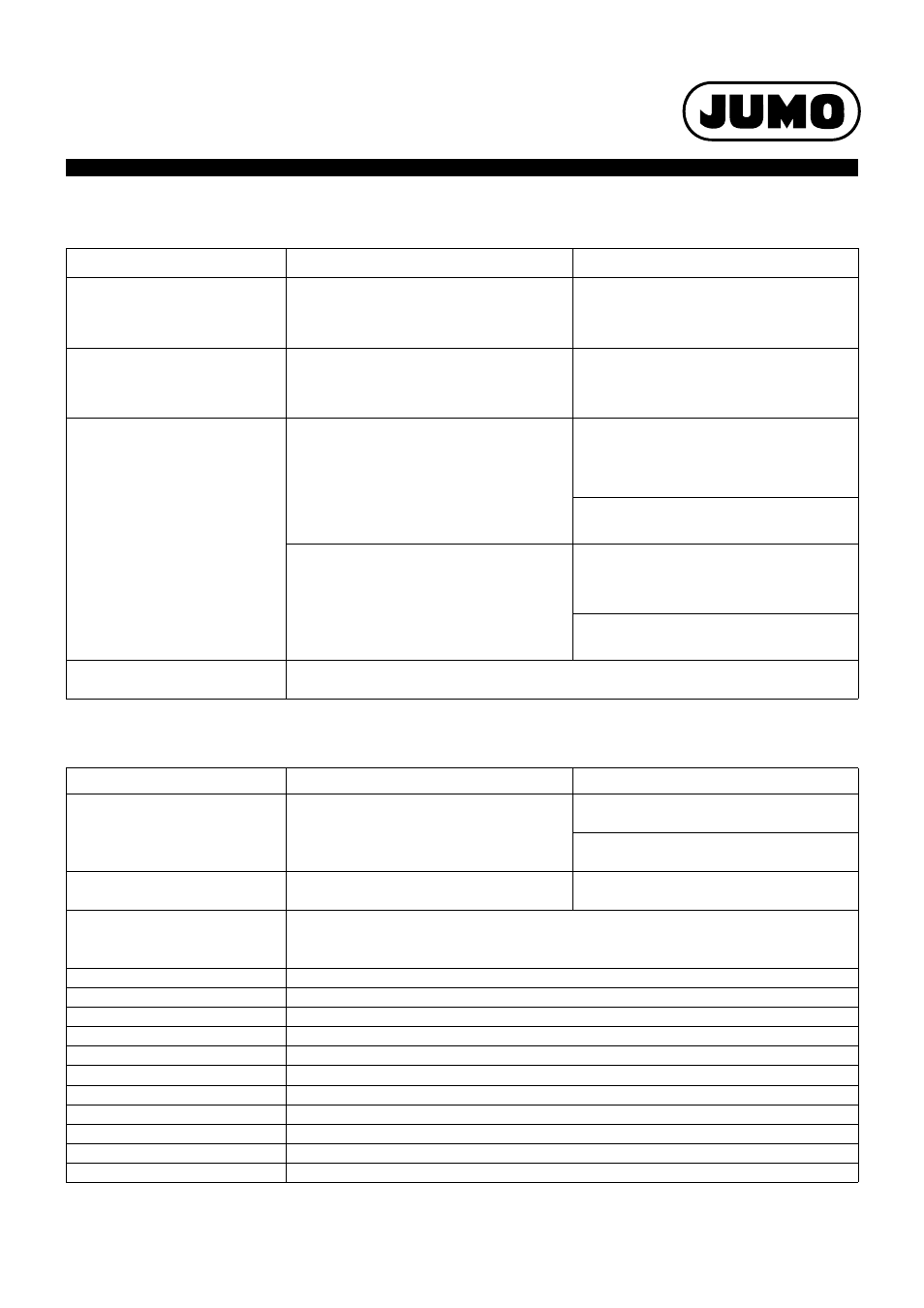
Measuring circuit monitoring
Output
Type 707050
Type 707051
Underrange
Linear drop up to 3.8 mA
Linear drop up to 3.8 mA
(According to NAMUR recommendation 43)
(According to NAMUR recommendation 43)
Linear drop up to -0.12 V
Overrange
Linear increase up to 20.5 mA
Linear increase up to 20.5 mA
(According to NAMUR recommendation 43)
(According to NAMUR recommendation 43)
Linear increase up to 10.31 V
Probe short-circuit/probe and
cable break
RTD temperature probe: (configurable)
RTD temperature probe: (configurable)
≤
3.6 mA,
≥
21.7 mA
≤
3.6 mA,
≥
21.7 mA
Or free setting: 3.6 mA to 23 mA
Or free setting: 3.6 mA to 23 mA
≤
-0.2 V,
≥
11.0 V
Or free setting: -0.25 V to 11.875 V
Thermocouple: (configurable)
a
a
For thermocouples and mV generator a probe short-circuit detection is not possible.
Thermocouple: (configurable)
a
≤
3.6 mA,
≥
21.7 mA
≤
3.6 mA,
≥
21.7 mA
Or free setting: 3.6 mA to 23 mA
Or free setting: 3.6 mA to 23 mA
≤
-0.2 V or
≥
11.0 V
Or free setting: -0.25 V to 11.875 V
Current limiting in the event of a probe
short circuit or probe break
≤
23 mA
Type 707050
Type 707051
Output signal
Load-independent direct current:
Load-independent direct current:
Free setting: 4 to 20 mA or 20 to 4 mA
Free setting: 4 to 20 mA or 20 to 4 mA
Voltage signal:
Free setting: 0 to 10 V or 10 to 0 V
Electrical isolation
Between input and output:
Between input and output:
Test voltage
Û = 3.75 kV/50 Hz
Û = 1.875 kV/50 Hz
Transmission behavior
Linear, temperature-linear
Customer specific
Reversion of the output signal
Step response 0 to 100 %
< 2 s (with filter constant 0 s)
Switch-on delay
5 s (correct measured value after the supply voltage is applied)
Current output
Load (R
b
)
R
b
= (U
b
- 11 V)/0.022 A
Load error
≤
±0.02 %/100
Ω
Calibration conditions/accuracy
DC 24 V at approx. 22 °C/±0.05 %
a
a
All specifications refer to the measuring range end value of 20 mA
Voltage output
Load resistance
≥
2 k
Ω
Load influence
± 15 mV
Residual ripple
± 1 % referring to 10 V, 0 to 90 kHz
Calibration conditions/accuracy
DC 24 V at approx. 22 °C/±0.05 %
b
b
All specifications refer to the measuring range end value of 10 V