Connection diagram – JUMO 701150 14597 safetyM STB/STW - Safety Temperature Limiter and Safety Temperature Monitor Data Sheet User Manual
Page 7
2012-07-01/00540116
Data Sheet 701150
Page 7/14
JUMO GmbH & Co. KG
Delivery address: Mackenrodtstraße 14
36039 Fulda, Germany
Postal address:
36035 Fulda, Germany
Phone:
+49 661 6003-0
Fax:
+49 661 6003-607
E-mail:
Internet:
www.jumo.net
JUMO Instrument Co. Ltd.
JUMO House
Temple Bank, Riverway
Harlow, Essex CM20 2DY, UK
Phone: +44 1279 635533
Fax:
+44 1279 635262
E-mail:
Internet: www.jumo.co.uk
JUMO Process Control, Inc.
8 Technology Boulevard
Canastota, NY 13032, USA
Phone: 315-697-5866
1-800-554-JUMO
Fax:
315-697-5867
E-mail:
Internet: www.jumousa.com
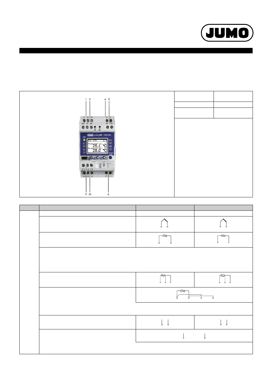
Connection diagram
The connection diagram in the data sheet provides preliminary information about the connection possibilities. For the electrical connection only
use the installation instructions or the operating manual. The knowledge and the correct technical execution of the safety information/instruc-
tions contained in these documents are mandatory for installation, electrical connection, and startup as well as for safety during operation.
The connection occurs via screw terminals.
Lead
Admissible cross
section
1 wire
≤
2.5 mm
2
Fine-strand,
with ferrule
≤
1.5 mm
2
Tightening torque of the screws:
max. 0.5 Nm
Legend:
Comment
Screw terminals
Screw terminals
1, 2
Analog input 1 (E1)
Analog input 2 (E2)
Thermocouple,
Double thermocouple
RTD temperature probe in 2-wire circuit
RTD temperature probe Pt100/Pt1000 in 3-wire circuit
RTD temperature probe Pt100 in
2-wire circuit, individual sensor for both analog inputs
Caution:
When only one probe (SIL2) is connected, the temperature limiter device is reduced from SIL3 to SIL2! However, the internal 2-channel struc-
ture(1oo2D) in the device is still retained. Both channels measure the same sensor due to the simplified external circuit.
(4) to 20 mA
(4) to 20 mA for both analog inputs
Caution:
When only one probe (SIL2) is connected, the temperature limiter device is reduced from SIL3 to SIL2! However, the internal 2-channel structure
(1oo2D) in the device is still retained. Both channels measure the same current signal due to the simplified external circuit.
+
–
2
3
+
–
7
8
J
1
3
J
6
8
A
Enter the lead wire resistance for RTD temperature probes in 2-wire circuit when using
greater line lengths.
Setup program: edit => analog inputs
1
2
3
J
6
7
8
J
J
1
3
6
8
2
3
+
–
I
x
7
8
+
–
I
x
2
+
–
I
x
7