Connection possibilities of the sensors (sil) – JUMO 701150 14597 safetyM STB/STW - Safety Temperature Limiter and Safety Temperature Monitor Data Sheet User Manual
Page 11
Page 11/14
Data Sheet 701150
2012-07-01/00540116
JUMO GmbH & Co. KG
Delivery address: Mackenrodtstraße 14
36039 Fulda, Germany
Postal address:
36035 Fulda, Germany
Phone:
+49 661 6003-0
Fax:
+49 661 6003-607
E-mail:
Internet:
www.jumo.net
JUMO Instrument Co. Ltd.
JUMO House
Temple Bank, Riverway
Harlow, Essex CM20 2DY, UK
Phone: +44 1279 635533
Fax:
+44 1279 635262
E-mail:
Internet: www.jumo.co.uk
JUMO Process Control, Inc.
8 Technology Boulevard
Canastota, NY 13032, USA
Phone: 315-697-5866
1-800-554-JUMO
Fax:
315-697-5867
E-mail:
Internet: www.jumousa.com
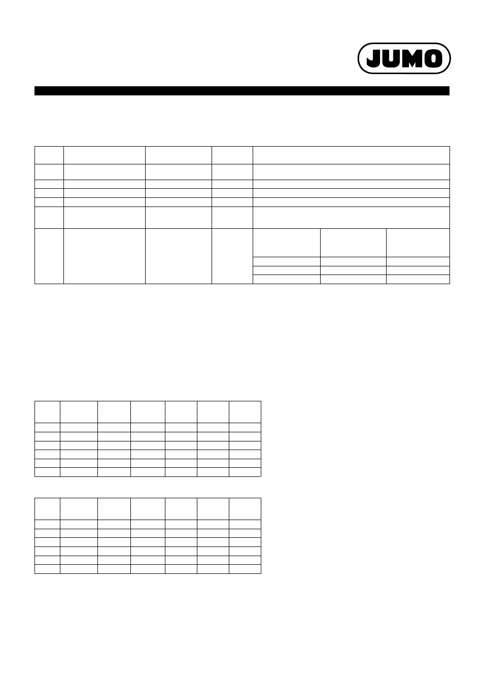
Connection possibilities of the sensors (SIL)
The JUMO safetyM STB/STW 701150 evaluation device structure is basically identical. Various possibilities to connect the sensors are available.
These possibilities are listed in the following table along with the achievable SIL level:
Note:
Variants 1 to 4 were evaluated with JUMO probes according to data sheets 901006 and 902006. For variant 5 no sensor system was taken into
account. In this case, the user selects the sensor system. For this reason, the user is responsible for evaluating the achievable SIL.
If the used SIL-capable sensor consists of hardware and software (e.g. transmitter), the maximum SIL that can be achieved —irrespective of the
architecture—is the one according to which the sensor software was developed (so, for example, if the sensor software has SIL 2, the max.
achievable SIL is 2).
The possibility to connect passive sensors such as double thermocouples, Pt100, or Pt1000 sensors means that the sensors do not necessarily
require a SIL qualification. In this case, the specification of the failure rates for the passive sensors is sufficient for the SIL qualification of the
overall system. The user of the system must always determine the PFD
avg
and/or PFH value of the overall safety circuit to evaluate the achieved
SIL.
Failure rates and SFF for 70.1150...23 (AC 240 V)
Failure rates and SFF for 70.1150...25 (AC/DC 24 V)
Note:
Variants 1 to 4 were evaluated with JUMO probes according to data sheets 901006 and 902006.
For variant 5 no sensor system was taken into account.
In this case, the user selects the sensor system.
The PFH and PFD
avg
values were calculated assuming that the time to restore the system is 8 h (MTTR = 72 h). Furthermore, the calculation was based on a lifetime
of 10 years (T
1
= 10 y). The Common Cause Factor was determined according to the tables of DIN EN 61508 for sensor systems and logic.
Variant
Connected sensors
Sensor system archi-
tecture
Logics archi-
tecture
Achievable SIL
1
1 × Pt100 in 2-wire circuit
individual sensor
1oo1
1oo2D
SIL2
1a
2x Pt100/1000 2-wire circuit
1oo2
1oo2D
SIL3
2
2x Pt100/1000 3-wire circuit
1oo2
1oo2D
SIL3
3
2x thermocouple
1oo2
1oo2D
SIL3
4
1x Pt100/1000
2-wire and 3-wire circuit
1x thermocouple
1oo2
1oo2D
SIL3
5
STB/STW 70.1150 without
sensor system 1oo2D archi-
tecture
no probe or use 4 to 20 mA
(means that the sensor is not
taken into account for the cal-
culation).
Sensors connected by
the system user
Architecture acc. to con-
nection 1oo1 or 1oo2
1oo2D
SIL of the used sensor
(HW only)
Max. achievable SIL of
the system with 1oo1
sensor system architec-
ture
Max. achievable SIL of
the system with 1oo2
sensor system archi-
tecture
SIL1
SIL1
SIL2
SIL2
SIL2
SIL3
SIL3
SIL3
SIL3
Variant
λ
s
[Fit]
λ
dd
[Fit]
λ
dd
[Fit]
SFF
PFH (1/h)
PFD
avg
1
865.21
306.24
32.31
96 %
4.56 e
-9
2.02 e
-4
1a
865.21
306.24
32.31
96 %
1.05 e
-9
4.57 e
-5
2
868.17
303.28
32.31
96 %
1.05 e
-9
4.57 e
-5
3
881.62
326.78
33.62
96 %
1.03 e
-9
4.49 e
-5
4
887.68
343.82
35.52
96 %
1.22 e
-9
5.30 e
-5
5
881.02
313.43
35.57
96 %
1.04 e
-9
4.48 e
-5
Variant
λ
s
[Fit]
λ
dd
[Fit]
λ
dd
[Fit]
SFF
PFH (1/h)
PFD
avg
1
799.3
306.32
33.61
96 %
6.59 e
-9
2.91 e
-4
1a
799.3
306.32
33.61
96 %
3.07 e
-9
1.35 e
-4
2
802.26
303.36
33.61
96 %
3.07 e
-9
1.35 e
-4
3
827.25
324.71
37.91
96 %
3.13 e
-9
1.37 e
-4
4
833.31
341.75
39.81
96 %
3.23 e
-9
1.41 e
-4
5
818.96
323.07
36.26
96 %
3.05 e
-9
1.33 e
-4