INFICON BCG450-SP ATM to Ultra-High Vacuum Triple Gauge (Profibus) User Manual
Page 8
8
tira41e1 (2005-06) BCG450SPv1.cp
Index
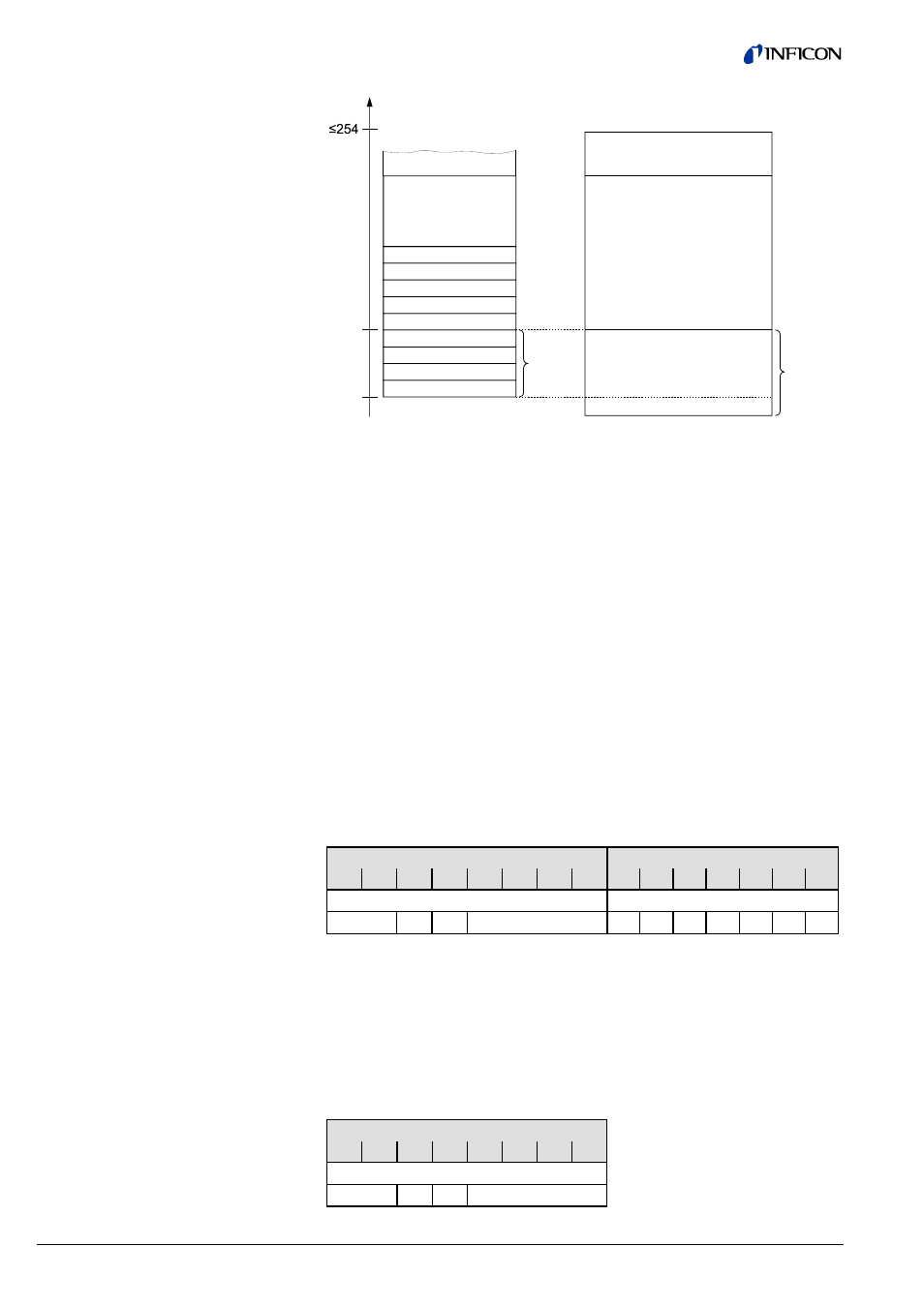
16
0
Private
Public
Operations Public
Block_x
Parameter_2
Parameter_1
Parameter_0
Operation_1
Operation_2
Operation_n
Parameter_n
Attributes
Block_Type_Name
optional
optional
In Data Exchange mode, the DP master class 1 cyclically transmits data from and
to all slaves that are connected to the bus.
In this document, data transmitted from the slave to the master are called "input
data" and data transmitted from the master to the slave are called "output data".
The input and output data of the BCG450-SP has two logic parts:
1) the parameter channel
2) the process data channel
There is a number of standard telegrams, consisting of:
a) the parameter channel only
b) the process data channel only
c) both, the parameter and process data channel
The parameter channels allows masters without Profibus DPV1 to access device
specific parameters that are not part of the normal cyclic data telegram. For mas-
ters with Profibus DPV1, no parameter channel is required.
The input data (transmitted by the BCG450-SP) consists of the 8 bytes of the pa-
rameter channel (if there is a parameter channel in the standard telegram) and of
5 … 7 bytes of process data depending on the selected standard telegram.
Byte
Byte
1
2
3
4
5
6
7
8
9
10
11
12
13
14
15
Parameter channel
Process data
PKE
IND res.
PWE
Where:
PKE
=
Parameter Signature Value
Reading or writing com-
mand and definition of the slot
IND
=
Sub Index
Index No. of the index to be
read (
→ "Block Model")
res.
=
reserved
PWE
=
Process Value
Value to be read or written
The output data (transmitted by the master) consist of 8 bytes of the parameter
channel or, if there is no parameter channel in the standard telegram, of 0 bytes.
Byte
1
2
3
4
5
6
7
8
Parameter channel
PKE
IND res.
PWE
Assignment of the block
elements to the slot indices
2.2 Structure of the Cyclic
Data Telegrams in
Data Exchange Mode
Input data
Output data