T3000 – INFICON T3000 Thermal Power Supply User Manual
Page 10
instruments
Thermal Power Supply
T3000
Section 1
Page 1 - 3
Introduction – Description
of Equipment
1.4 Output
Characteristics
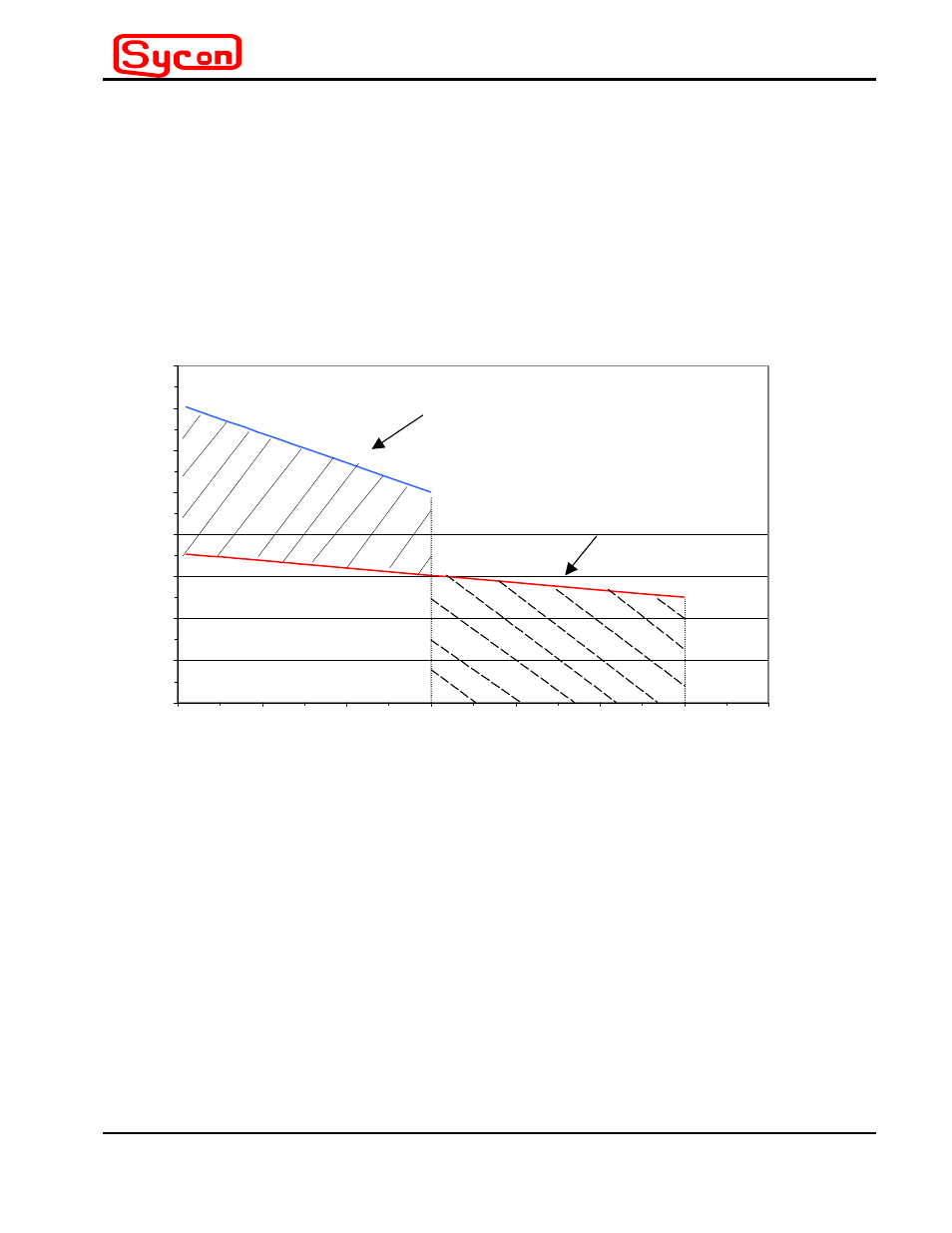
The purpose of this subsection is to provide guidelines for choosing between series or
parallel output connections based on the load requirements of the thermal source being
energized. Output voltage and current profiles vary in proportion to load resistance, up to
maximum limits determined by the output circuit configuration. Figure 1-1 provides a
guideline for choosing the appropriate output hookup configuration, based on the T3000
maximum output profile and the load requirements of the thermal source.
Maximum Load Voltage-Current Profile
0
2
4
6
8
10
12
14
16
0
100
200
300
400
500
600
700
Load Current - Amps RMS
Load V
o
ltage - V
o
lts RMS
Max Output: Parallel Configuration
Max Output: Series Configuration
Series Only Region
Parallel Region Only
Either Series or Parallel Region
Vline = 220V rms
Figure 1-1
Maximum Voltage-Current Profile for Series and Parallel Hookup
Figure 1-1 is marked with regions which define when the series or parallel output
configuration is appropriate. The maximum voltage-current rating of any given thermal
source may be located as a point on the graph. The appropriate configuration(s) is
determined by the location of this point.
For example, consider a commercially available thermal source rated at 521 ARMS and a
corresponding voltage drop of 3.89 VRMS. This is a 2kW thermal source and falls in the
area of the graph noted as “Parallel Only”.
By way of contrast, a thermal source rated at 742 Watts, which is specified by a voltage
drop of 8.73 VRMS at 85 ARMS and falls in the “Series Only” region of the graph.