INCRA TS-LS Table Saw Fence User Manual
Page 5
The rail positions described above will provide support for
the base of the TS-LS for work on either the left or right
side of the blade. Left hand range is about 16” and right
hand range is 32” or 52” depending on your rail length.
If you wish to customize the setup to suit your needs, just
slide the rails left or right as necessary. Keep in mind
that sliding the rails to the right subtracts from your range
to the left, and sliding the rails to the left subtracts from
your range to the right.
Set final mounting bracket position
Clamp the (2) TS-LS base clamps to the front rail
as shown in Fig. 4 and loosen the bolts that secure the
mounting brackets to your table saw. The rail and mounting
brackets will drop down until the base clamps touch the top
of your saw, Fig. 5. This locates the final mounting bracket
position. Tighten the bolts that secure the mounting brackets
to your table saw. Repeat for the rear rail.
Mounting
bracket
FIG. 4
Set final mounting
bracket position
Base clamps
Clamp pad
Rail
Mounting
bracket
First: Clamp base clamps to rail.
Use clamp pads to avoid marring
anodized surfaces
Second: Loosen both mounting
bracket bolts. Brackets will
lower slightly
Set final rail position
Loosen the bolts that secure the main rails to their
mounting brackets and slide the rails so that they extend 45”
to the right of the saw blade (for 72”-long rails) or extend 65”
to the right of the blade (for 92” rails) as shown in
Fig.6. Push
the rail against the short vertical leg on the mounting bracket
and tighten the bolts that hold the rail in place. See
Fig. 7
below.
NOTE: If you have also purchased a router table
extension wing, complete all assembly instructions in this
manual BEFORE attaching the router table.
4
5
FIG. 5
Tighten
mounting
bracket
bolts
Base clamp
Table saw top
Mounting
bracket bolt
Mounting bracket is at
correct level when base
clamp touches table top
INCRA TS-LS Owner’s Manual
5
Custom Setups
Short vertical leg
FIG. 7
Tighten rail
mounting
bolts
Push rail against
short vertical leg
and tighten rail
mounting bolts
Rail mounting bolt
Rail
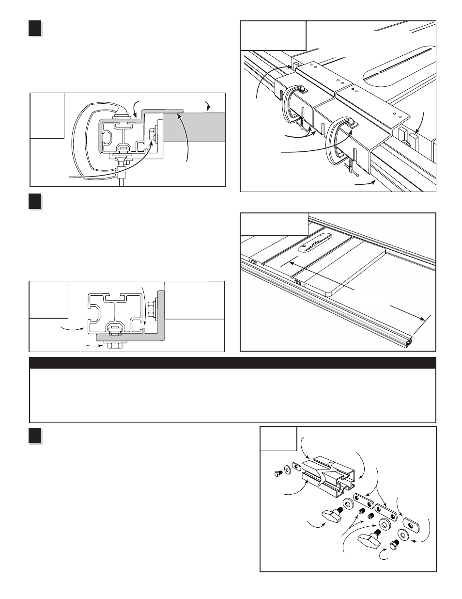
Slide stop positioner and base clamping
knob assemblies onto the rails
Base clamping knob - Add a
3
⁄
16
” thick nylon washer to each of
(4) base clamping knobs and loosely attach a
3
⁄
8
–16 dual pilot
rectangular nut. The flat side of the rectangular nut should face the
knob. Thread a
3
⁄
8
–16 x
3
⁄
8
” set screw into the remaining hole on
each rectangular nut. Slide the base clamping knob assemblies
onto the right hand end of each rail as viewed from the operator’s
side of the table saw. Do not tighten set screws or knobs at this
time. See Fig. 8.
Stop positioner - Add a
3
⁄
8
” flat washer to each of (4)
3
⁄
8
–16 x
1
⁄
2
”
hex bolts, then loosely attach a
3
⁄
8
–16 rectangular nut. Slide one
stop positioner into each end of both rails, capturing the rectangular
nut in the T-slot as shown. Do not tighten bolts at this time.
6
FIG. 8
Assembly
Do not tighten
fasteners at this time
3
⁄
8
” flat
washer
3
⁄
8
– 16 x
1
⁄
2
”
hex bolt
Base clamping knob
3
⁄
16
” thick
nylon washer
3
⁄
8
– 16 x
3
⁄
8
” set screws
3
⁄
8
– 16
rectangular
nut
3
⁄
8
– 16 dual pilot
rectangular nuts
T-slot
Left end of rail
Right end
of rail
FIG. 6
Set final rail position
45” (72” rails)
65” (92” rails)