Warranty, Auxiliary fence mounting, Maintenance – INCRA TS-LS Table Saw Fence User Manual
Page 12
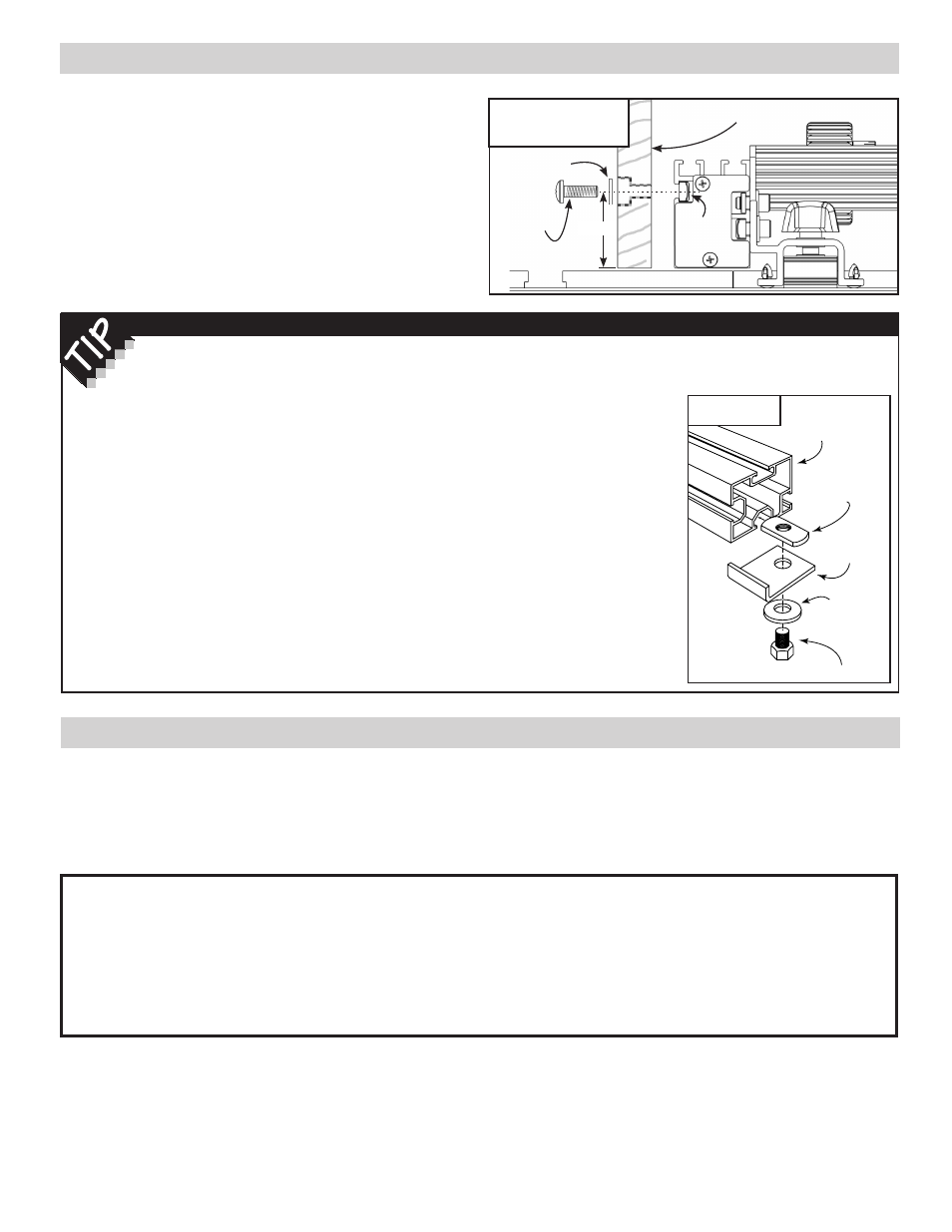
AuXILIARY FENCE MOuNTING
For some cutting operations, you may wish to add a wooden
auxiliary fence to the front face of your TS-LS fence. A
T-slot is provided for mounting the auxiliary fence using
1
/
4
-20 mounting screws, washers, and hex nuts. Drill and
counterbore your wooden fence to recess the screw heads
and capture the nuts in the T-slot as shown in Fig. 29. Hole
centers should be located 1
3
/
4
” from the bottom edge of the
wooden fence. T-slots in the top of the fence are provided to
attach hold downs or other user-made fixtures. Use
1
/
4
-20
fasteners and hex nuts for these T-slots as well.
Made in America by:
Taylor Design Group, Inc.
P.O. Box 810262
Dallas, Texas 75381
Tel: (972) 242-9975
Fax: (972) 243-4277
Web Site: www.incra.com
Printed in the U.S.A. © 2003 Taylor Design Group, Inc.
INCRA is a registered trademark of Taylor Design Group, Inc.
fig. 29
Auxiliary fence mounting
Wooden auxiliary fence
1
/
4
” flat
washer
1
/
4
– 20
screw
1
/
4
–20
hex nut
WARRANTY
Taylor Design Group, Inc. warrants this product for one year from date of purchase. We will repair any defects due
to faulty material or workmanship, or at our option, replace the product free of charge. Please return the failing
component only, postage prepaid, along with a des cription of the problem to the address below. This warranty does
not apply to parts which have been subjected to improper use, alteration, or abuse.
MAINTENANCE
Your TS-LS is designed to give many years of virtually
maintenance-free operation. In fact, just keeping your
TS-LS clean is all you need to do to keep the tool in top
shape. Occasionally, remove the carriage from the base
and brush or blow out any sawdust or debris that may
have accumulated. Use a toothbrush to clean the teeth on
the lead screw on both the carriage and the base. A light
application of paste wax to the top of the rails from time to
time will keep the rails smooth and clean.
10/12
Included with your TS-LS package you’ll find
the
Floating Stop Hardware Pack B-05. These
stops mount to the bottom T-slot on the rails and are
used when you want to set stop positions for the base
assembly anywhere between the fixed left or right hand
stops located on the sides of the rails.
One reason for a mid-range stop position might be to
provide a single position for the base assembly where
one could access both the saw blade and the left hand
router table extension wing. Such a setup would provide
about 15”-16” of range at the table saw function and
up to 30” of travel for the router function. To install the
stops, place a washer on each end of the (2)
3
/
8
-16 x
1
/
2
” hex bolts. Insert the bolt through the hole in the stop
and loosely thread on the rectangular nut. Slide the nut
into the bottom T-slot from the right end of each rail. See
Fig. 30. After positioning the LS along the rails at the
desired location, slide the floating stops up to the base
clamps and tighten the bolts.
Once positioned, you
can still slide the base
assembly past the stops
if necessary by first
disengaging the fence
hooks and loosening the
(4) base clamp knobs, then
lifting the base assembly
just enough to clear the
stops as you slide the
base assembly forward or
backward.
fig. 30
12
INCRA Woodworking Tools & Precision Rules
Floating Stops
Floating
stop
3
/
8
– 16
rectangular
nut
Right hand
end of rails
3
/
8
” flat
washer
3
/
8
-16 x
1
/
2
” hex bolt
1
3
/
4
”