Wonder fence installation, Super system only), Adjusting the fence angle – INCRA LS Positioner User Manual
Page 8: Mounting an auxiliary fence to your pro ii fence
8
INCRA Woodworking Tools & Precision Rules
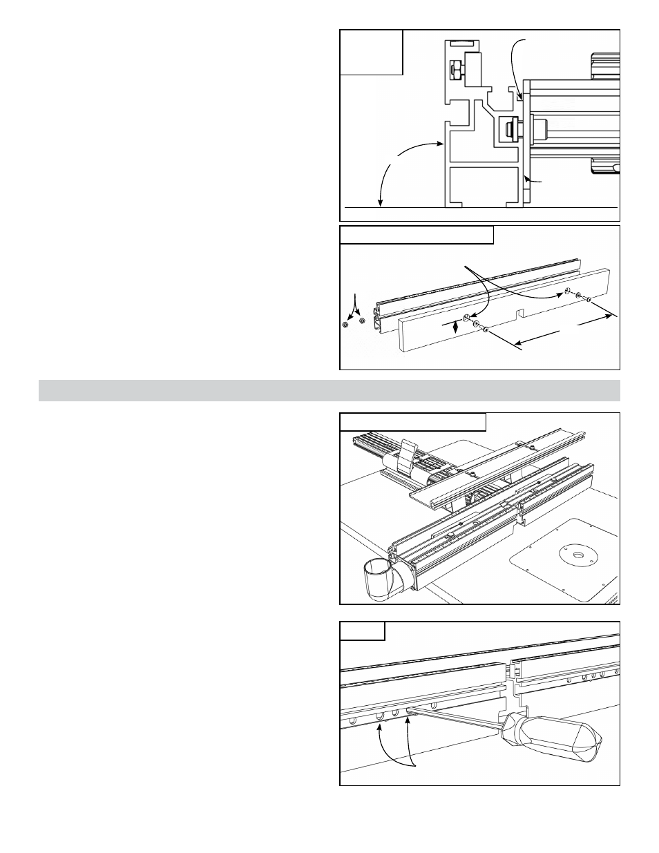
Adjusting the Fence Angle
After mounting the Pro II Fence, pull the carriage
clamp up to the fully locked position and check the
angle of the fence to your tabletop using a reliable
square. Any deviation from 90° can be adjusted to
perfection by placing a masking tape shim between
the mounting bracket and the fence as shown in
Fig. 11.
Mounting an Auxiliary Fence to
your Pro II Fence
Should you have an application requiring the use
of a user-made wooden auxiliary fence, you’ll find
the T-slot in the front face of the Pro II Fence is
designed to capture a ¼-20 hex nut. Just use the
dimensions in Fig. 12 to drill and counterbore the
fence, then use (2) ¼-20 Phillips pan head screws,
(2) ¼” flat washers, and (2) ¼-20 hex nuts to secure
the auxiliary fence to the Pro II Fence. Adjust the
length and thickness of the fence to accommodate
your application.
Place shim here if
angle is greater
than 90º
90º
Place shim
here if angle is
less than 90º
WOnDer FenCe InStAllAtIOn
(SuPer SYSteM OnlY)
While you should read the Safety, Operation and
Applications
sections of the included Wonder
Fence owner’s manual, it is not necessary
to read the Fence and Hi-Rise mounting
instructions in that manual. Just follow the
instructions below for proper mounting of the
Wonder Fence and Hi-Rise Fence Cap to your
LS Positioner.
Attaching the Wonder Fence
to the Pro II or tS Fence
Note:
In the 17” (430mm) and 25” Super System
packages, the Wonder Fence front fence halves
are shipped already installed onto the Pro II Fence;
however, you should read and become familiar
with the following installation procedure for future
adjustments or removal.
Insert the supplied hex tool through the (2) large
diameter access holes located on the front of
each Wonder Fence half and loosen the (2) socket
head screws. Do not remove the rectangular
nuts. For a better view of the fasteners, loosen the
thumbscrew and slide the black plastic view panel
located on the top of each fence half, Fig. 13.
FIg. 13
¼-20 hex
nuts
14”
1¾”
5
/
16
” dia. through holes with
3
/
4
” dia. counterbore
Use hex tool to loosen fasteners
through two larger holes
FIg. 12
Mounting an auxiliary fence
FIg. 11
Adjusting the
fence angle
LS Positioner Super System