Pro ii fence installation – INCRA LS Positioner User Manual
Page 6
6
INCRA Woodworking Tools & Precision Rules
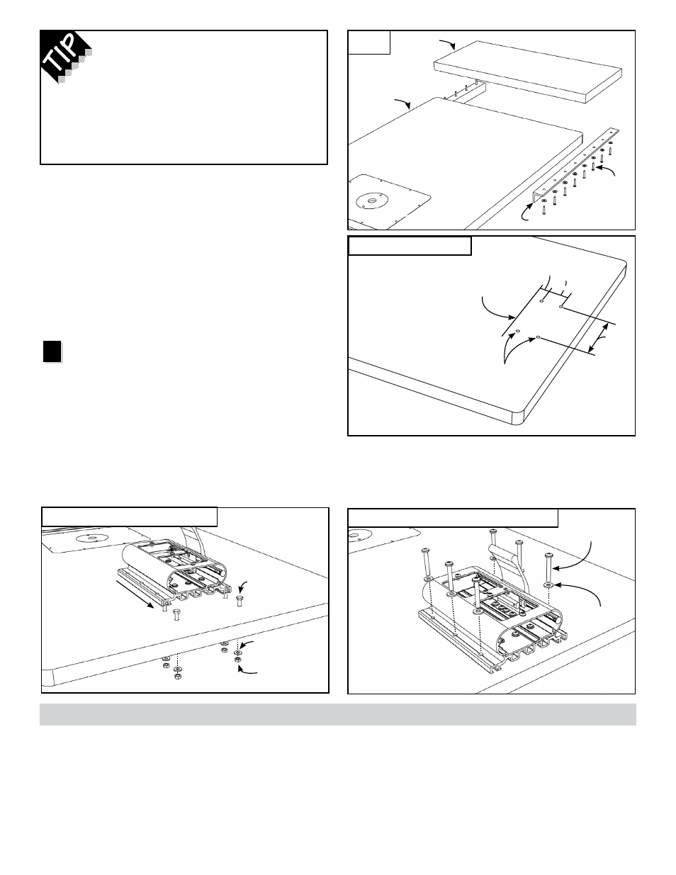
Once you have determined where the leading edge
of the LS Base will be positioned, mark a line on the
table at this spot. The line should be parallel to the
back edge of your router table. Measure back 1”
from this line and mark positions for (2)
5
/
16
” diameter
mounting holes spaced 5½” apart. Measure back
another 2” further and mark positions for (2) more
5
/
16
” diameter holes,
Fig. 4. (If your table permits,
increase the spacing between the 2 sets of holes.)
Drill the holes.
Attach lS Base to your router
table
Open the
LS Base Mounting Hardware Pack A-21.
Place the (4) ¼-20 x 2” hex bolts through the holes in
the table and loosely fasten with ¼” washers and hex
nuts. Now slide the heads of the bolts into the T-slot
located on the underside of the LS Base,
Fig. 5.
Square the base to your table edge and tighten the
fasteners. Now slide the carriage back into the base
and pull the carriage clamp up to lock the carriage in
place.
FIg. 3
Extension
wing
2
Extending your router table length
Screw aluminum or steel angle to the
underside of the router table to provide
support arms for a table extension, Fig. 3.
The extension needs to be flush and parallel
to the table top. Shim into alignment as
necessary.
Existing
router
table top
Wood
screws
Aluminum or steel angle
5½”
Drill
5
/
16
” diameter holes
Mark where leading
edge of LS Base will
be positioned
1” 2” minimum
Slide LS
Base onto
heads of hex bolts
¼-20 x 2” hex bolt
¼” flat washer
¼” hex nut
¼-20 x 1¾” pan
head Phillips screws
¼” flat washer
PrO II FenCe InStAllAtIOn
(StAnDArD & SuPer SYSteM OnlY)
Note: If you have an “Incra ready” router table with
T-nuts installed in the pre-drilled mounting holes, use
the (6) ¼-20 x 1¾” pan head Phillips screws with ¼”
washers to attach the LS Base as shown in
Fig. 6.
The Pro II Fence, included in both the Standard
and Super System packages, provides a 28”
long reference for all of your cutting operations.
Machined to perfection, it includes a 1” x 1” opening
to handle all of your grooving, dadoing, rabbeting
and joinery applications. The fence top includes
INCRA positioning racks that work in conjunction
with the INCRA Shop Stop for perfectly repeatable
stopped cuts. The self-storing stop extender bar
permits stopped cuts beyond the length of the
fence and the front T-slot allows easy attachment of
user-made sub fences or the Super System Wonder
Fence.
FIg. 6
Mounting for “Incra Ready” router table
FIg. 4
Drill mounting holes
FIg. 5
Attach LS Base to router table