Graff BATH MIXER (with Wall-Mount Spout) User Manual
Page 11
IOG 2328.50
Rev. 1 December 2007
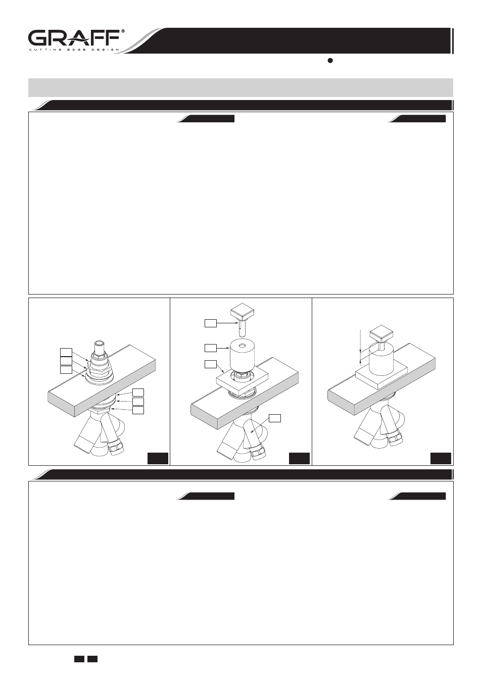
DIVERTER VALVE INSTALLATION
•
INSTALACIÓN DE LA VÁLVULA DE DESVIADOR
See fig. 2, 9.1-9.3
1. Unscrew the top nut (26) and remove the two washers
(27 & 28) from the valve.
2. Insert the diverter valve (31) along with the lower nut
(26) and the washers (29 & 30) through the assembly
hole in the bath.
3. Place the washers (28 & 27) on to the valve from above in
the order shown in fig. 9.1 and screw on the top nut (26),
but not too strongly.
4. Place the base of the valve cover (25) onto the valve from
above and screw on the valve cover (24), then screw the
knob (23) onto the valve. Check that the distance rema-
ining between the upper surface of the cover (24) and
the lower surface of the knob (23) is sufficient to allow
the switch to function correctly (it should measure around
25/64”(10mm)) - see fig. 9.3. If the distance is not suffi-
cient, adjust it using the nuts (26).
5. After choosing the appropriate distance, tighten up the top
nut (26). Replace the base of the valve cover (25) on the
valve and screw on the valve cover (24) until resistance is
clearly felt, then screw the knob (23) onto the valve.
Ver diseńos 2, 9.1-9.3
1. Destornille la tuerca superior (26) y quite dos arandelas
de la válvula (27 y 28).
2. Inserte la válvula desviadora (31) con la tuerca inferior
(26) y las arandelas (29 y 30) ponga por el agujero de
montaje en la bañera.
3. Desde arriba en la válvula ponga las arandelas (28 y 27)
de acuerdo con el dis. 9.1 y ponga la tuerca superior (26),
pero no la aprietes demasiado.
4. Desde arriba en la válvula ponga la base de la cubierta
de la válvula (25) y ponga la cubierta de la válvula (24),
después en la válvula ponga la bola (23). Compruebe si la
distancia dejada entre la superficie superior de la cubierta
(24) y la superficie interior de la bola (23) es suficiente
para el buen funcionamiento del conmutador (debería ser
aproximadamente de 25/64” (10 mm)) - ver el dis. 9.3.
Si no lo es, corrija la distancia con las tuercas (26).
5. Tras elegir la distancia adecuada apriete bien la tuerca su-
perior (26). Ponga de nuevo la base de la cubierta de
la válvula (25) en la válvula y apriete la cubierta de la
válvula (24) hasta el momento de sentir una resistencia
notable, después en la válvula ponga la bola (23).
ESPAÑOL
ENGLISH
SHOWER HANDSET INSTALLATION (and connecting shower handset to the diverter valve)
See fig. 10
1. Position the shower base (19) in the axis of the assembly
hole.
2. Insert shower handset socket (18) through the hole in the
deck.
3. From underneath the ledge place rubber washer (20)
on the shank, then screw on the flanged nut (21). Hand
tighten only.
4. Make sure that the shower handset socket (18) and sho-
wer base (19) are in proper position on the bath ledge.
Tighten the flanged nut (21) using adjustable wrench.
5. Insert the shower hose (17) through the shower handset
socket (18) by its narrow end. Connect the shower hand-
set (15) to the hose (17), taking care that the flat seal
(16) is positioned correctly in the coated shower hose nut.
Screw the other end of the hose (17) into the casing of the
diverter valve (31), keeping in mind the positioning of the
flat seal (22).
Ver el dis. 10
1. Posisione la base de la ducha (19) en el eje del agujero de
montaje.
2. Inserte el asiento de la ducha (18) a través del agujero en
la cubierta.
3. Por debajo del borde coloque la arandela de goma (20)
en el tubo de conexión, luego enrosque la tuerca con brida
(21). Apriete únicamente a mano.
4. Asegúrese de que el asiento de la ducha (18) y la base de
la ducha (19) se encuentran en la posición apropiada en el
borde de la bañera. Ajustela tuerca con brida (21) usando
la llave inglesa.
5. Ponga la manguera de ducha (17) de un lado más fino
por el asiento dela ducha (18). Junte la ducha (15) con
la manguera (17), verifique si la posición de la empaque-
tadura plana (16) está colocada bien en la tuerca galva-
nizada de la manguera de la ducha. Otra boquilla de la
manguera (17) ponga en el cuerpo de la válvula de des-
viador (31), recuerdeponer la empaquetadura plana (22).
ESPAÑOL
ENGLISH
INSTALACIÓN DE LA TELEDUCHA (y conectado la teleducha a la válvula de desviador)
DIVERTER VALVE & SHOWER HANDSET INSTALLATION
INSTALACIÓN DE LA VÁLVULA DE DESVIADOR Y DE LA TELEDUCHA
26
29
30
26
27
28
23
24
25
31
~0.4" (10mm)
9.1
9.2
9.3
11
GB E
BATH MIXER (with Wall-Mount Spout)
EL GRIFO DEL BAÑO (con Caño Montado en la Pared)
Installation Instructions Instrucciones de instalación