Led control, 3 led control – GeoDesy FSO GeoData20 series User Manual
Page 53
53
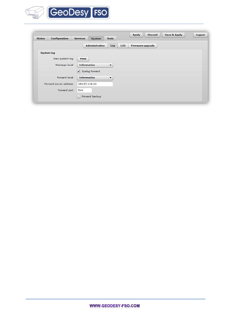
View system log
– click to view current trace messages. The system log viewer utility provides debug
information about the system services and protocols. If the device's malfunction occurs recorded
messages can help operators to locate misconfiguration and system errors.
Message level
– specify system's message tracing level. The level determines the importance of the
message and the volume of messages generated by the device. The levels are in increased
importance order [emergency, alert, critical, error, warning, notice, information, debug]. Default: info.
The device can be configured to send system log messages to a remote server:
Syslog forward
– select to enable remote system logging.
Forward server
– specify the remote host IP address or hostname where syslog messages will be
sent.
Forward port
– specify the port to which syslog messages will be forwarded [0-65535]. Default: 514.
Forward message level
– specify the level of the message which will be sent to the remote syslog
server. The level determines the importance of the message and the volume of messages generated
by
the
device.
The
levels
are
in
order
of
increasing
importance
[emergency/alert/critical/error/warning/notice/information/debug]. Default: information.
Forward backup
– select to enable remote syslog logging backup.
Backup server
– specify the backup host IP address or hostname where syslog messages will be
send to.
Backup port
– specify the port to which syslog messages will be forwarded [0-65535]. Default: 514.
7.4.3 LED Control
The APC is equipped with 6 LEDs: power, LAN and 4 RSSI LEDs that indicates the signal strength of
current connection. The signal level is classified into 4 levels, thus corresponding 4 LEDs switches on
as soon as indicated threshold is reached.