General Machine Products 70400 Apollo Cable Lasher User Manual
Page 15
15
4.6.2 Lashing wire termination
1. Secure the lashing wire to the strand with a lashing wire grip before cutting
or otherwise releasing tension in the lashing wire. The lashing wire grip should
be placed far enough from where the supports, spacers and lashing wire clamps
are to be installed to avoid having to move the grip.
Note: The situation can exist where the .038 in. (0,97 mm) dia. lashing wire
may nest in the space between the wires of the 10M strand. Ensure that the D
lashing wire grip is securely contacting both the lashing wire and the strand to
prevent loss of tension in the lashing wire.
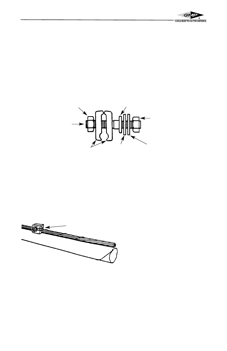
4.6.3 Lashing wire clamps
Figure 25, D Lashing Wire Clamp
1. The D or E lashing wire clamp may be used with .038 (0,97 mm) and .045
(1,1 mm) dia. lashing wire on strand sizes of .25 to .38 in. (6 to 10 mm) diame-
ter (6M, 6.6M and 10M).
2. The nuts of the clamp are tightened and loosened with the 7/16 in. end of a
216C tool or B ratchet wrench.
Figure 26, Terminating Lashing Wire
4.6.4 Terminating lashing wire using D or E lashing wire clamps
See figure 26 for steps 1, 3 and 4.
1. The lashing wire clamp should be located 2 inches outside of the first lashed
cable support or cable suspension clamp. The lashing wire should be wrapped
twice around the strand and then terminated on the cable lashing clamp.
Clamping Nut
Threaded Stud
Grooved Plates
2nd Washer
1st Washer
Shoulder
Form the end of the lashing wire
around the end of the clamp as shown