L1 l2 r y b – Flint & Walling 4 (10 cm) Stainless Commander S Series User Manual
Page 9
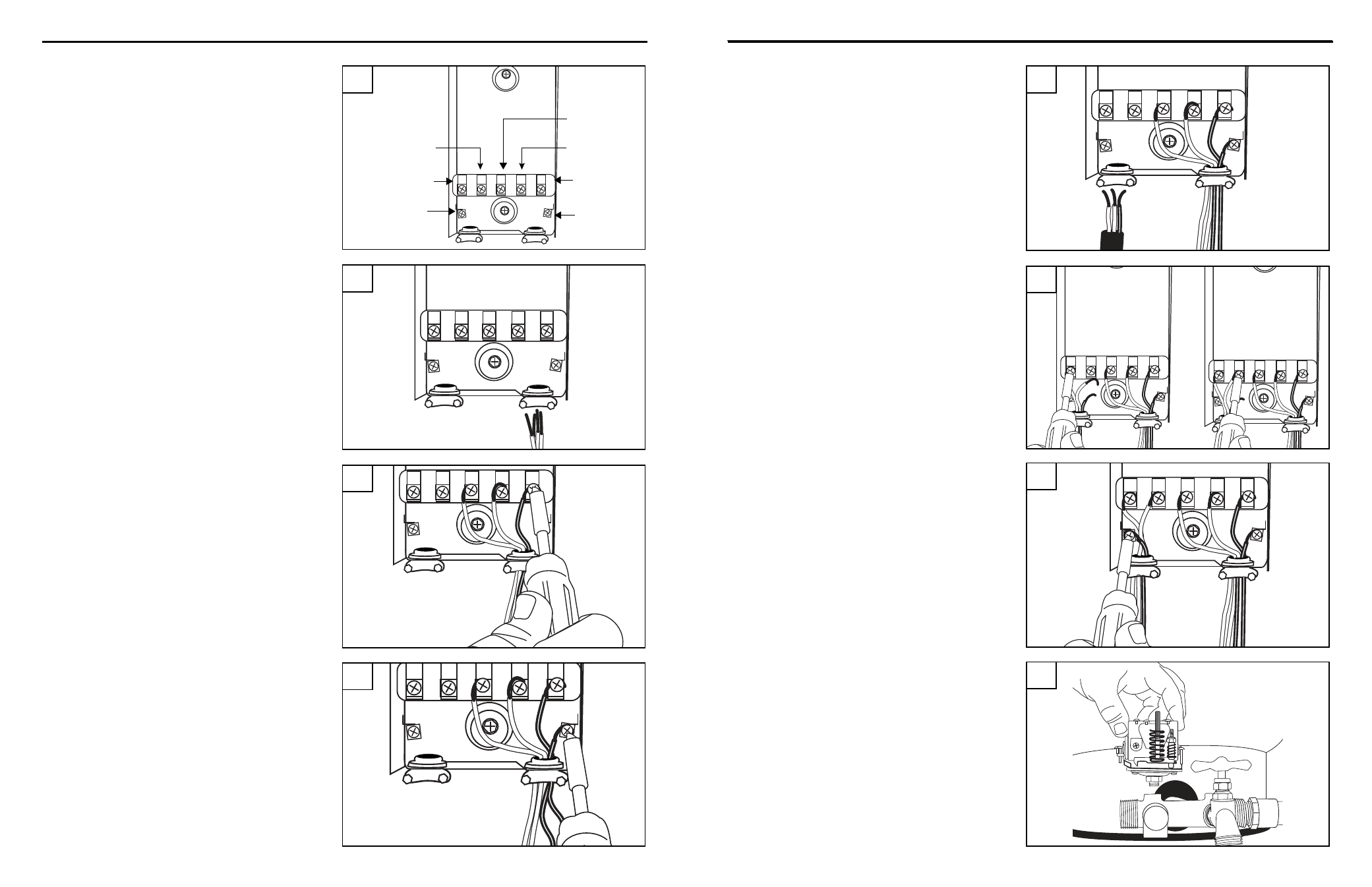
16
Copyright © 2014 Flint & Walling. All rights reserved.
17
Copyright © 2014 Flint & Walling. All rights reserved.
ElECTRICAl HOOKuP FROM THE HOuSE TO PuMP ANd PRESSuRE TANK
2. Remove the cover from the control box and
mount it in an indoor location protected from
moisture.
(Fig. 2)
ElECTRICAl HOOKuP FROM THE HOuSE TO PuMP ANd PRESSuRE TANK
4. Attach the black, yellow and red wires to the
appropriate terminals marked “B”, “Y” and “R”.
(Fig. 4)
5. Connect the green ground wire from the pump to
the green ground screw in the lower right corner
of the control box.
(Fig. 5)
3. Thread the electrical wire from pump into the
right opening in the bottom of the control box
and tighten the electric wire strain relief securely.
(Fig. 3)
L1 L2
R
Y
B
Terminal
L2
Terminal
R
Terminal
Y
Terminal
B
Green
Ground
Screw
Terminal
L1
Green
Ground
Screw
2
L1 L2
R
Y
B
IL1176
L1 L2
R
Y
B
IL1175
4
5
L1 L2
R
Y
B
IL1174
3
L1 L2
R
Y
B
IL1177
6
L1 L2
R
Y
B
IL1178
L1 L2
R
Y
B
IL1179
7
L1 L2
R
Y
B
IL1180
8
9
9. Remove cover from pressure switch and screw
the switch into the 1/4 in. opening on the top of
the pipe tee.
(Fig. 9)
6. Thread the electrical wire from the pressure
switch into the left opening at the bottom of the
control box and tighten the electric wire strain
relief securely.
(Fig. 6)
7. Connect the two wires from the pressure switch
to the terminals in the control box marked L1 and
L2.
(Fig. 7)
8. Connect the green ground wire from the pressure
switch to the green ground screw in the lower left
corner of the control box and re-install the control
box cover.
(Fig. 8)