4a 4b – Flint & Walling 4 (10 cm) Stainless Commander S Series User Manual
Page 5
8
Copyright © 2014 Flint & Walling. All rights reserved.
9
Copyright © 2014 Flint & Walling. All rights reserved.
ElECTRICAl HOOKuP AT THE PuMP
5
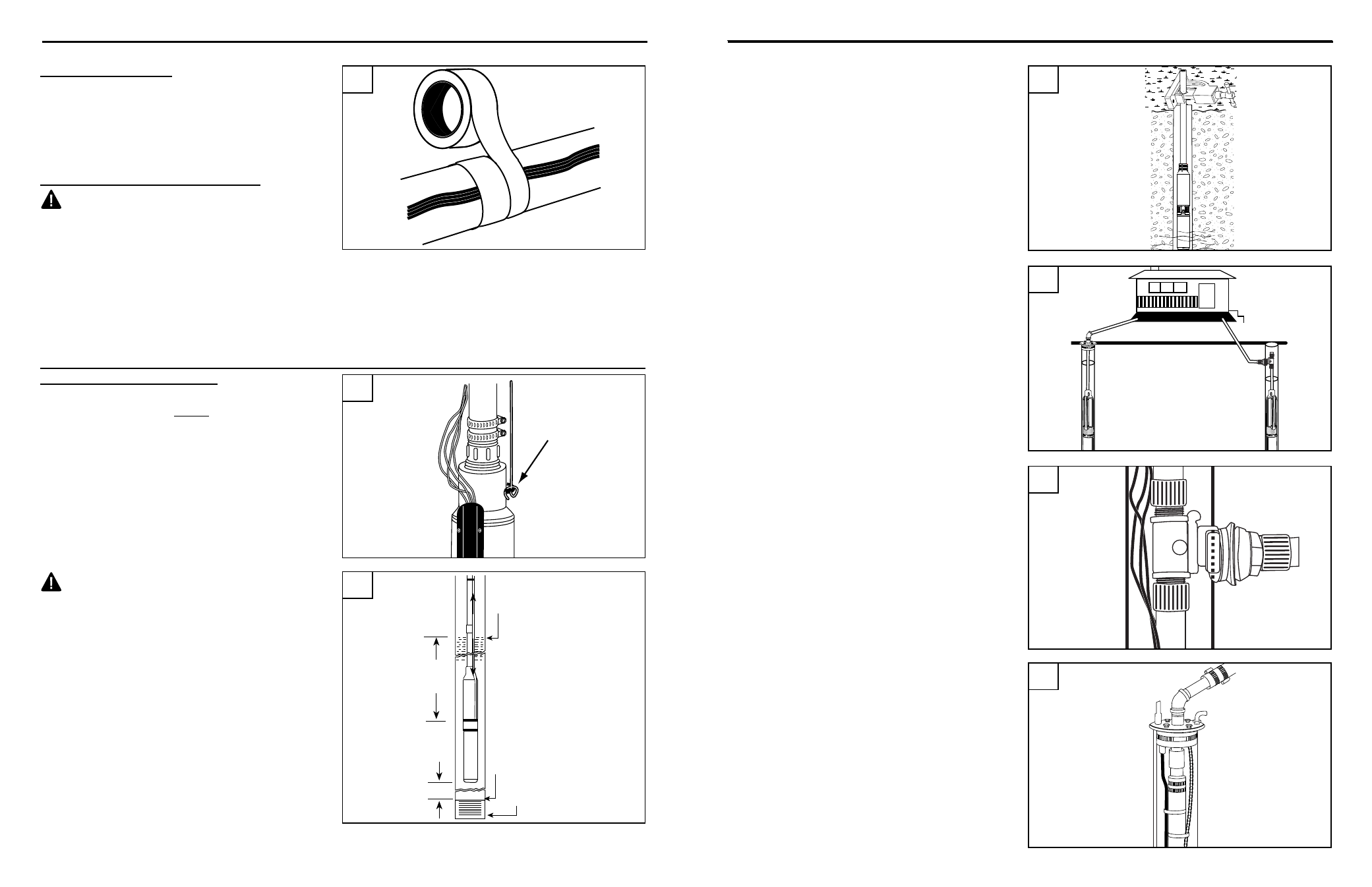
Securing wires to pipe
5. Tape electrical cable to the pipe about every
ten feet. Use a minimum of two wraps of tape
to allow the cable to move slightly. Tape spliced
connections to the pipe to eliminate rubbing
against the well casing. A cable guard or plastic
zip ties may also be used.
(Fig 5)
Ground wire Installation (REQuIREd)
dANGER: The green ground wire from Pump
motor must be connected to power supply ground
or fatal electrical shock may result.
INSTAllATION
lOwERING PuMP INTO wEll
REMINdER: Pump and all piping must be assembled
and securely connected before the assembly is
lowered into the well.
1. Tie one end of safety rope securely to pump safety
eyelet and the other end to the well cap. This is your
only security against losing the pump down the well.
(Fig 1)
CAuTION: Be sure the top edge of the well
casing is perfectly smooth. Sharp or jagged edges
can cut or scrape the cable and cause a short.
Do not let the cable drag over the edge of the
well casing since this may cause damage to the
insulation.
2. Lower pump to approximately 20 ft. below
maximum drawdown of the water or a minimum
of 10 ft. off the bottom.
do NOT set pump on
bottom of well.
(Fig 2)
3. Use a pipe vise to prevent the pump and pipe
from dropping into the well.
(Fig 3)
Safety
Rope
Drawdown
Water Level
10 Ft. Min.
20 Ft.
Top of Well Screen
Bottom of Well
1
2
INSTAllATION
4a. Pitless Adaptor Installation. Pitless adaptor
should be installed below the frost line, and on
the side of the well casing where the supply
line will run from well, in accordance with the
manufacturer’s instructions.
(Fig. 4a)
NOTE: Pitless adaptor models vary according to
each application.
4b. Well Seal Installation: After the pump assembly
is lowered into the well, mount the well seal
onto the well casing and tighten the four bolts in
the well seal evenly.
(Fig. 4b)
4. Add a well seal or pitless adaptor to allow for the
pipe to be connected to house service.
(Fig. 4)
3
IL1148
4a
4b
Pitless
Adaptor
Installation
Below
Frost Line
Well Seal
Installation
At Top of
Well Casing
OR
4