FasTest JXL Series User Manual
Operating instructions, Dimensional information: jxl external lever action, Collet set removal and installation
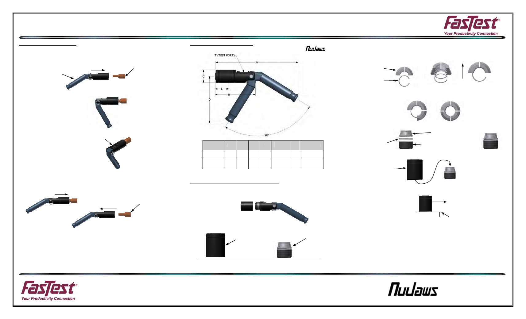
OPERATING INSTRUCTIONS
www.fastestinc.com
® Roseville, MN
Ph 1-800-444-2373
Fax 651-645-7390
WP013 04/2009
TEST PIECE
TEST PIECE
Operating Instructions:
Connecting Action:
1. Place lever in the in-line position then insert connector onto test piece. Make sure
test piece is inserted to the required minimum insertion length (see chart). This will
assure proper location relative to the main seal.
2. Rotate lever 90 degrees to the grip and seal position.
Note: Preferred position of lever
as shown with test media port on top.
3. Introduce test media through test port.
Disconnecting Action:
1. Vent test media pressure.
2. Rotate lever to the in-line position to release gripping action.
3. A slight forward motion of the connector toward the test piece opens the locking
collets.
4. Remove connector.
Note: The safety design of the pressure assisted gripping collets will not release
under pressure.
CAUTION: If excessive operating force or stickiness of the collet/seal assembly is
noted, remove collet/seal assembly (See Collet Set Removal and Installation:) and
check for alignment and lightly lube the bore of the housing with a petroleum jelly
or other compatible lubricant.
Dimensional Information:
JXL EXTERNAL LEVER ACTION
BODY SIZE
A
B
C
D
MAX
FLOW Ø
L
T
JXL0
7.25
3.65
1.12
4.13
.24
.79
1/8-27 NPTF
JXL1
7.25
3.58
1.62
4.22
.37
.85
1/4-18 NPTF
(L=Minimum Insertion Depth)
Collet Set Removal and Installation:
Collet Removal:
1. Place lever in the in-line position with housing (A) pointed downward, unscrew from
body (B). Use finger to keep main seal (F), washer (E) collets (D) and retaining rings
(C) inside housing (A).
2. Keeping all components inside housing
place housing on flat surface then lift housing off of internal components.
3. Collet Set components are now exposed for inspection or replacement.
Collet Installation:
1. First step, assemble collet segments (D) and retaining rings (C), form two pieces of
collets into a half circle and hold between thumb and middle finger. The raised
portion of the collets should be toward your thumb with the retaining ring groove
facing out.
2. Place the retaining rings (C) into the grooves in collets.
3. Add the last two pieces of collets to form a circle. Hold collet assembly together in
one hand.
4. Stack as shown. Set the collet assembly, largest side down, on the washer.
5. Place housing (A), threaded side first, over the completed collet assembly stack.
6. Slide the housing/collet assembly to the edge of the table and as you slide it off the
edge use your index finger to hold the seal/collet assembly in place inside housing.
7. Push on the seal, washer and collet assembly from the back to move it to the front
of the housing.
8. Turn housing over so that the threaded end is pointed up and screw connector body
onto housing. Tighten hand tight until the body o-ring (G) seals. The piston
assembly that contains the test port may also rotate. This can be realigned after the
housing is snug.
9. If collets are not aligned properly in the seal casing, the casing will not thread on
completely. When this occurs, loosen the housing and adjust the collet assembly,
you may have to start procedure again from step #1 above.
10. With collet in place and housing snugly tightened, rotate the lever to actuate
connector. Visually verify that the connectors gripping and sealing action is correct.
Continued on other side:
INSERT CONNECTOR
TEST MEDIA PORT
GRIP & SEAL
POSITION
CONNECT/
DISCONNECT
POSITION
ROTATE LEVER 90° FOR
GRIP AND SEAL ACTION
LEVER IN-LINE
POSITION
GRIP & SEAL
POSITION
REMOVE CONNECTOR
SLIGHT FORWARD MOTION
HOUSING (A)
COLLET SET
COMPONENTS
F, E, D & C
HALF CIRCLE
FINGER SIDE
RINGS INTO
GROOVES
MAIN SEAL (F)
BEVEL SIDE DOWN
WASHER (E)
COLLET SEGMENTS (D)
AND RETAINING RINGS (C)
SLIDE
FINGER/TABLE EDGE
(D)
(C)
(A)