Operating instructions, Chart 1: fi connector dimensions, Chart 2: fastest fi connector seals – FasTest FI Series User Manual
Page 2: D: mounting of connector fi model connector, E: attaching pressure lines fi(m) model connector, F: connector operation
FasTest Inc. 1646 Terrace Drive Roseville, MN 55113 Phone: 651-645-6266 Toll Free: 800-444-2373 www.fastestinc.com
Operating Instructions
Chart 1: FI Connector Dimensions
FI
A
C
D
E
F
K*
L*
FI01, FI01M
1.98
1.25
10-32 UNF,
M5X8
10-32 UNF,
1/8 BSPP
0.80
10-32 UNF,
M5X8
0.53
FI1, FI2, FI1M, FI2M 2.44
1.57
1/8** NPSF,
1/8 BSPP
1/8** NPSF,
1/8 BSPP
1.02
1/4-28 UNF,
M6X1.0
0.59
FI3, FI4, FI3M, FI4M 2.60
2.36
1/8** NPSF,
1/8 BSPP
1/8** NPSF,
1/8 BSPP
1.60
1/4-28 UNF,
M6X1.1
1.08
FI5, FI6, FI5M, FI6M 3.66
3.49
1/2** NPSF,
1/2 BSPP
1/2** NPSF,
1/2 BSPP
2.31
1/4-28 UNF,
M8X1.25
1.61
FI7, FI8, FI7M, FI8M 3.36
4.20
3/4** NPSF,
3/4 BSPP
3/4** NPSF,
3/4 BSPP
3.00
1/4-28 UNF,
M6X1.25
1.63
*L = Minimum insertion length of test piece
** Can be used with BSP or NPT male fittings
Chart 2: FasTest FI Connector Seals
Model
FIS Seal
Set
Sealing Range
No of Seals
Max Flow
FI01,
FIO1M
01
1/8NPT*
.330-.394
1
2
0.060"
FI1,
FI1M
11
1/4NPT*
12
13
.394-.472
.472-.551
.551-.630
1
2
1
1
0.130"
FI2,
FI2M
3/8NPT*
21
1/4NPT*
22
23
.630-.709
.709-.797
.787-.866
2
1
2
1
1
0.17"
FI3, FI3M
31
3/4NPT*
32
33
.866-.945
.945-1.024
1.024-1.102
2
2
2
2
0.21"
FI4, FI4m
41
1NPT
42
43
1.102-1.181
1.181-1.260
1.260-1.339
2
2
2
2
0.28"
FI5, FI5M
51
52
1-1/4NPT
53
1.339-1.457
1.457-1.575
1.575-1.693
3
3
3
3
0.56"
FI6, FI6M
61
1-1/2NPT
62
63
1-693-1.852
1.850-2.008
2.008-2.185
3
3
3
3
0.72"
FI7, FI7M
71
2NPT
72
73
2-1/2NPT
2.185-2.305
2.305-2.445
2.445-2.585
3
3
3
3
3
0.92"
FI8, FI8M
81
82
83
2.585-2.725
2.725-2.865
2.865-3.005
3
3
3
0.92"
* Main Seal is neoprene. NPT seals are urethane. FI NPT seals sets
contain a urethane main seal with additional neoprene face seal.
** FI NPT seal sets include a face seal.
Note: “M” Designates metric customer interface. See Chart 1 for metric
mounting hole thread sizes.
D: Mounting of Connector
FI model connector
The test connector must be secured to the test piece with a mechanical
E: Attaching Pressure Lines
FI(M) model connector
1. Attach pilot pressure line to pilot port “E”, Diagram 3. A pneumatic
related source is required to maximize seal life and assure
optimum seal-ability for the application. The pilot pressure should
be minimized to maintain sealing on the test piece without
excessive compression of seal. Excess pilot pressure may
reduce the life of the seal.
2. Attach test media line to test port “D”, Diagram 3.
3. Provide a means whereby test pressure will not be introduced
until pilot pressure required to seal is reached. The means should
also provide quick exhaust of test pressure in the event pilot
pressure falls below the minimum required to seal.
Pilot Pressure. Regulate pilot pressure to the minimum required pressure
for sealing under test conditions (pressure or vacuum). Use of minimum
required pilot pressure will prolong seal life. Generally, a 60 to 90 psi
pneumatic pilot pressure source is required.
Test Pressure. Maximum rated test pressure for standard FI models is
120 psi. With connector secured and pilot activated, introduce gas or liquid
through the FasTest FI connector until desired testing, filling or flushing is
complete.
FasTest, Inc. Product Warranty
FasTest, Inc. warrants its products against defects of workmanship and/or material for 1 year from
the date of the sale by FasTest, Inc. This warranty is void if the product is misused, tampered
with or used in a manner that is not in accordance with FasTest, Inc. recommendations and/or
instructions. FasTest, Inc. is not liable for consequential or other damages including, but not limited
to, loss, dam-age, personal injury, or any other expense directly or indirectly arising from the use of
or inability to use its products either separately or in combination with other products. ALL OTHER
WARRANTIES EXPRESSED OR IMPLIED, WHETHER ORAL OR WRITTEN, INCLUDING BUT
NOT LIMITED TO WARRANTIES OR MERCHANTABILITY OR FITNESS FOR A PARTICULAR
PURPOSE ARE EXPRESSLY EXCLUDED.
Remedy under this warranty is limited to replacement of the product or an account credit in the
amount of the original selling price, at the option on FasTest, Inc. All allegedly defective products
must be returned prepaid transportation to FasTest, Inc. along with information describing the
products performance, unless disposition in the field is authorized in writing by FasTest, Inc.
or other device to assure the connector is not uncoupled from the test
piece by the uncoupling force of the test itself. The securing or holding
device may be a fixture, clamp, cylinder or other appropriate means that
prevents ejection of the test piece from the connector.
Uncoupling force example:
Test piece has a ½” O.D. and is tested at 100 psi maximum. Uncoupling
force = area (π r
2
) x pressure = π.25
2
x 100 = 20 lbs. Secured device
should be designed to withstand this force and include an adequate
margin for safety. Do not activate the connector without an adequate and
safe securing mechanism.
Mount the FasTest FI connector to the fixture or appropriate device using
either threaded mounting holes on the rear of the connector body, or
appropriate adapter.
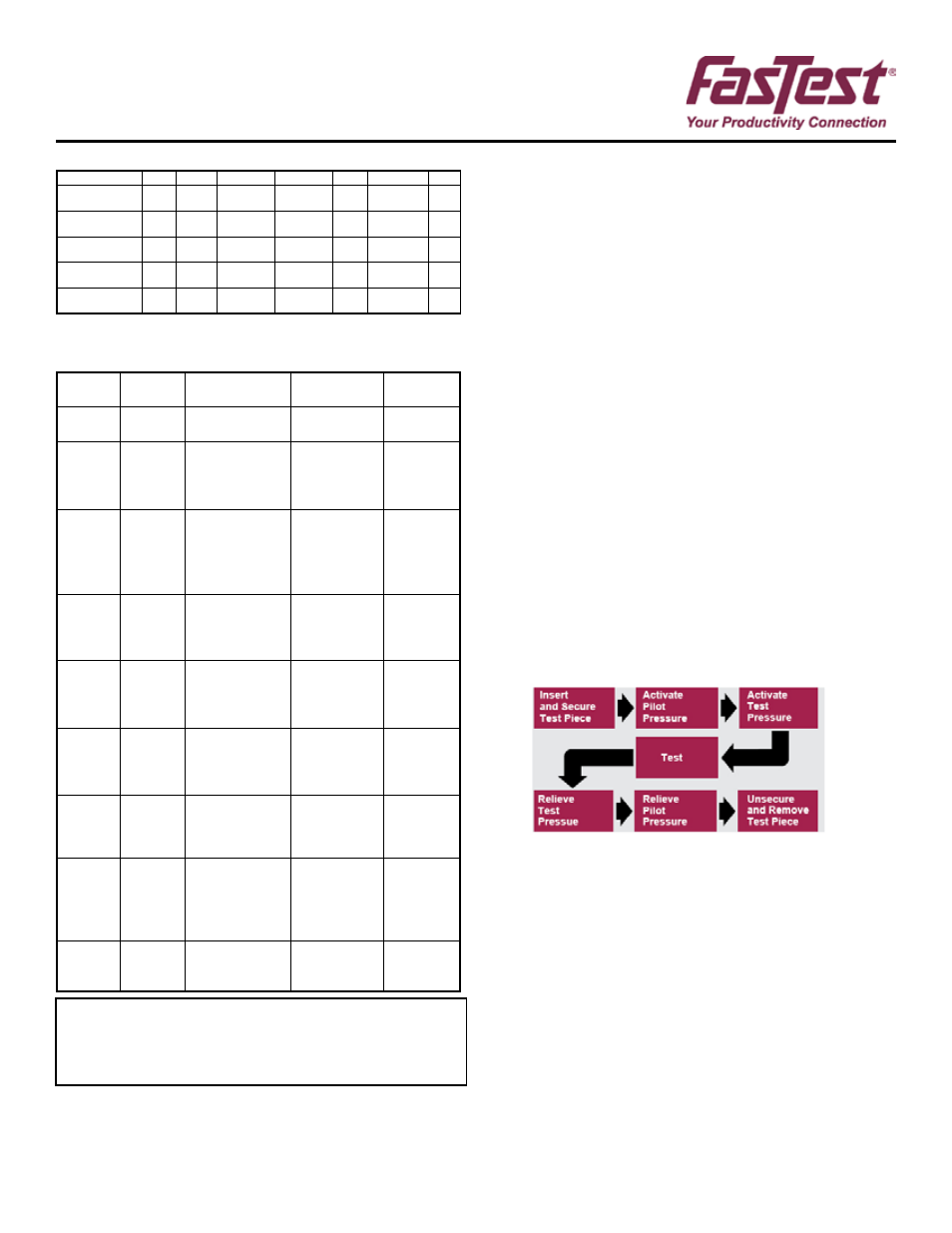
F: Connector Operation
FI Model connector into ports, tubes, etc.
WARNING: The FI connector must be SECURED to the test piece by a
mechanical device before proceeding.
Activate connector testing sequence as shown below
WP008 1/2009 rev. C