4 technical data, Technical data, Manual eks light and light fsa 5.4 technical data – EUCHNER FSA Light User Manual
Page 24
Manual EKS Light and Light FSA
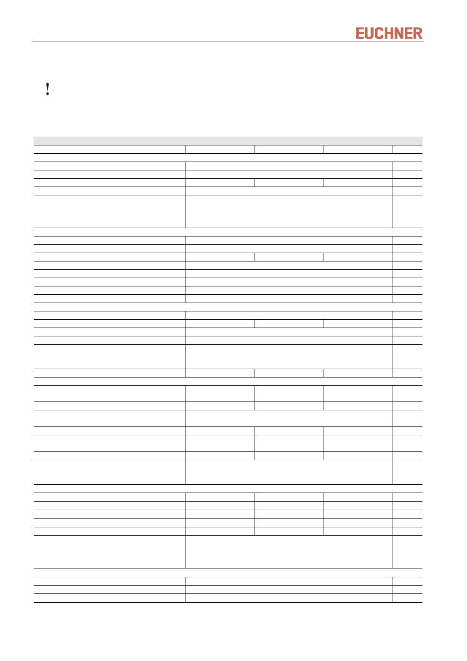
5.4 Technical data
Attention!
All the electrical connections must either be isolated from the mains supply by a safety transformer
according IEC 61558-2-6 with limited output voltage in the event of a fault, or by other equivalent
isolation measures. Pin 0V of the supply voltage is electrically connected to the housing in the compact
version.
Value
Unit
min.
typ.
max.
General parameters of Electronic-Key adapter compact
Housing
Plastic (PA 6 GF30 gray/black)
Degree of protection according to EN 60529
IP 65, IP 67 in mounted condition
Ambient temperature at U
B
= DC 24 V
-20
+ 70
°C
Mounting cut-out acc. to DIN 43700
33 x 68
mm
Connection type for power supply, outputs and
semiconductor switching contact (FSA)
2 plug-in screw terminals, 2- and 5-pole
2 plug-in screw terminals, 4- and 5-pole (FSA version)
Conductor cross section 0.14 … 1.5 mm²,
tightening torque 0.22 Nm
General parameters of Electronic-Key adapter Front Hook Modular FHM
Housing
Plastic (PVDF GF30 gray)
Degree of protection according to EN 60529
IP 65, IP 67, IP 69K in installed state
Ambient temperature
-20
+70 /+100*
°C
Mounting hole
Ø 22.5
mm
Connection
Cable fixed to Electronic-Key adapter, with flying lead
Connection cable length
2
m
Connection cable cross-section
4 x 0.25 screened
mm²
Connection cable outer sheath
PVC
General parameters of interface adapter modular
Housing
Plastic (PA 6.6)
Ambient temperature at UB = DC 24 V
-20
+70
°C
Mounting
35-mm DIN rail acc. to DIN EN 60715 TH35
Connectable Electronic-Key adapter
1
Connection type for power supply, outputs,
Electronic-Key adapter and semiconductor
switching contact (FSA)
4 plug-in screw terminals, 4-pole,
Conductor cross-section 0.14 ... 2.5 mm²
Cable length to Electronic-Key adapter
2
15
m
Electronics, interface and signaling
Operating voltage U
B
(regulated, residual ripple < 5 %)
9 24 28
DC
V
Current consumption I
B
(without load current)
70
mA
Interface to inputs of control system or switch
unit
4-bit parallel plus strobe, binary coded via High/Low level
Load current per output I
A
1
10
50
mA
Output voltage U
A
(High level) for
A,B,C,D, strobe
U
B
- 2
U
B
V
Cable length to control
50
m
LED indicator
green “Ready” (in operation)
yellow “Electronic-Key active” **
red “Error”
FSA version (For Safety Applications) – parameters for floating semiconductor switching contact LA
Power supply for load U (LA)
24
30
V
Switching current (with overload protection)
1
10
50
mA
Output voltage U
A
(LA) in switched state
U x 0.9
U
V
Resistance in switched state
35
Ohm
Capacitive load
1
µF
Utilization category according to AC-12
EN IEC 60947-5-2 AC-15
DC-12
DC-13
50 mA / 24 V
Reliability values according to EN ISO 13849-1 (only FSA version)
Category (with connected safe evaluation)
3
MTTF
d
200
years
DC
92 %
* This is not the ambient temperature for operation. It is valid for a time duration of max. 3 minutes, e.g. for cleaning purposes.
** The LED illuminates yellow if there is a valid Electronic-Key in the Electronic-Key adapter.
Page 24/40
Subject to technical modifications
110845-04-03/12