7 led indicator, Led indicator, Manual eks light and light fsa 5.7 led indicator – EUCHNER FSA Light User Manual
Page 27
Manual EKS Light and Light FSA
5.7 LED indicator
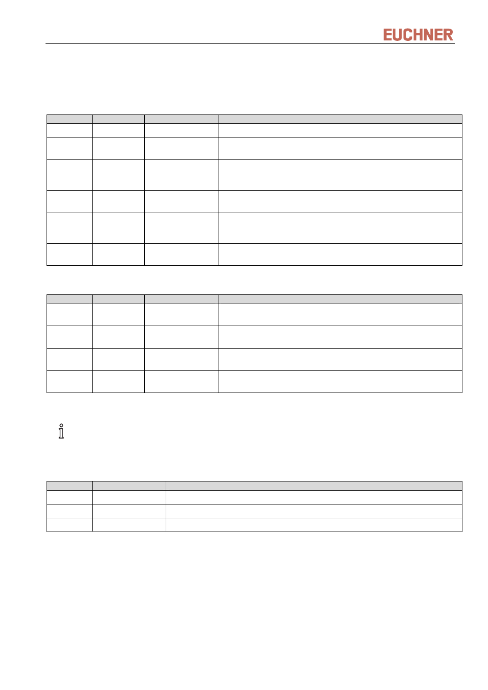
The operating status of the Electronic-Key adapter is indicated via the LED on the front by means of three colors
in combination with static illumination or illumination in various flashing sequences.
Signaling and flashing sequences in normal operation and in the event of errors:
Color
Signal
Operating state
Description
green static
Ready Key adapter is ready.
yellow static Electronic-Key
active, access
A valid Electronic-Key is in the Electronic-Key adapter, and user access
is approved.
green/yello
w
flashing
no access
The access code programmed on the Electronic-Key does not match the
access code setting in the device. Check the Electronic-Key
programming and the setting of the DIP switch.
green/yello
w
flashing 1x
briefly yellow
no access
Checksum (CRC) is not conclusive. Check the Electronic-Key
programming. There may have been a tampering attempt.
green/yello
w
flashing
2x briefly
yellow
no access
The operating state programmed on the Electronic-Key does not match
the operating state setting in the device. Check the Electronic-Key
programming and the setting of the DIP switch.
green/yello
w
flashing 3x
briefly yellow
no access
The access level programmed on the Electronic-Key does not match a
value possible in the current operating state.
The device will enter the fault state if the following errors occur:
Color
Signal
Operating state
Description
red flashing
1x briefly
no access
Reserved for future application. Check the settings of the DIP switch.
red flashing
2x briefly
no access
The parity bit check within the DIP switch in the device is not conclusive.
Check the settings of the DIP switch.
red flashing
3x briefly
no access
The operating state set on the DIP switch is not available. Check the DIP
switch settings.
red flashing
≥4x briefly
no access
Device defect (hardware). Please return device for checking to Euchner.
Information!
In order to terminate the fault state the device must be restarted. Interrupt the power supply for at least
2 seconds.
The operating status of the interface adapter is additionally signaled by means of three LEDs in three colors:
Color
Designation
Description
green
STATE
Interface adapter ready
yellow
ACTIVE
Signaling of Electronic-Key recognition as described in the table above.
red
DIA
Diagnostics, signaling of an error as described in the table above.
110845-04-03/12
Subject to technical modifications
Page 27/40