1 description of operating state 0, 2 dip switch settings in operating state 0, 3 operating state (os) (bit nos. 10 to 13) – EUCHNER FSA Light User Manual
Page 16: 4 access code (ac) (bit nos. 0 to 9), Description of operating state 0, Dip switch settings in operating state 0, Operating state (os) (bit nos. 10 to 13), Access code (ac) (bit nos. 0 to 9), Manual eks light and light fsa
Manual EKS Light and Light FSA
4.3.1 Description of operating state 0
An operating state (OS), an access level (AL) and an access code (AC) are stored on the Electronic-Key (see
section 8 Parameter assignment of the Electronic-Keys via the Electronic-Key-Manager EKM software). If an
authorized user is recognized via a valid Electronic-Key, the outputs on the read station (also referred to as
device below) are set to High in accordance with the stored access level values. All values on the Electronic-
Key must lie within the possible value range. All outputs are reset to Low when the Electronic-Key is withdrawn.
An Electronic-Key can access a suitably set read station via the access code. An unlimited number of
Electronic-Keys can be programmed with the same access code (e.g. user group). An unlimited number of read
stations can have the same access code set via the DIP switch (e.g. installation group).
The access code is 10 bits long. These 10 bits are available on the DIP switch for setting and in the Electronic-
Key for programming (binary coding). The access code results from the setting of individual bits (bit setting =
value 1) on the DIP switch in the device and the setting of individual bits in the access code on the Electronic-
Key. Unique values from 0 to 1023 are possible for the access code. In operating state 0, only an exact match
of the bit pattern between the Electronic-Key and device will lead to access.
If access is released via the access code, the strobe signal will be set and the access level will be statically
issued with one of 16 possible levels via the 4-bit data wire as long as the Electronic-Key remains inserted.
The derivation of access rights to machine functions according to the output of the access level is carried out
through the control at the user’s location.
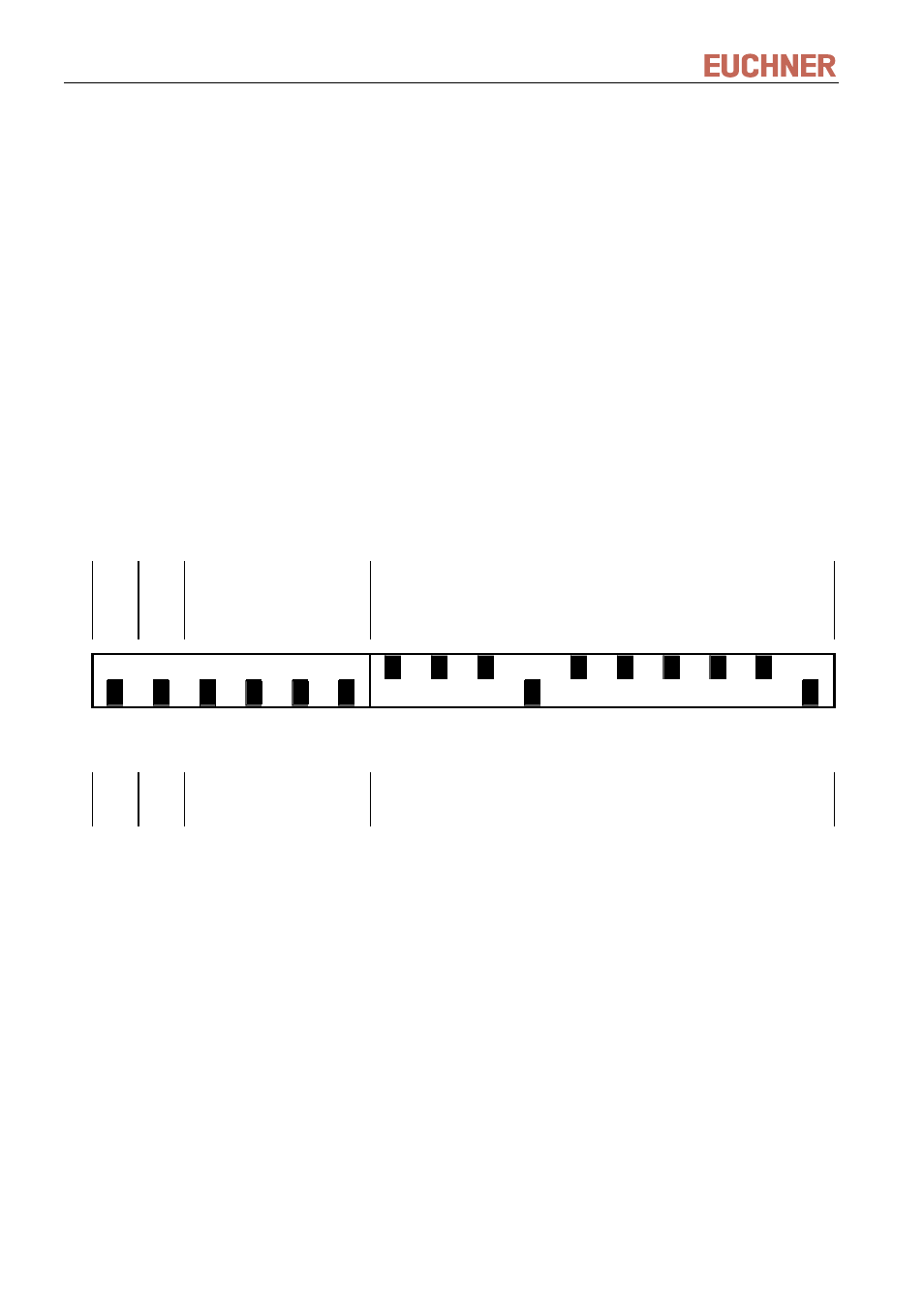
4.3.2 DIP switch settings in operating state 0
Bit
no.
15
14
13
12 11
10
9 8 7 6 5 4 3 2 1 0
MSB
LSB
MSB
LSB
1 bit
1 bit
4 bits
10 bits
ON
OFF
S1.1
S1.2
S1.3
S1.4
S1.5
S1.6
S2.1
S2.2
S2.3
S2.4
S2.5
S2.6
S2.7
S2.8
S2.9
S2.10
Even
parity
No
funct.
Operating State OS
Value: 0
dec
Access Code AC
Sample value: 958
dec
4.3.3 Operating state (OS) (bit nos. 10 to 13)
The operating state is set in binary form using switches S1.3 to S1.6. The value is always 0 for operating state
0; all switches S1.3 to S1.6 are therefore set to OFF. Operating state 0 is the factory setting.
4.3.4 Access code (AC) (bit nos. 0 to 9)
The access code is set in binary form using switches S2.1 to S2.10. An access code therefore results from the
bit pattern of the set bits. Values from 0 to 1023 (10 bits) are possible.
Page 16/40
Subject to technical modifications
110845-04-03/12