Operating instructions read head cem-a-le05h-s2, Setting adhesive force, Service and inspection – EUCHNER CEM-A-LE05H-S2 User Manual
Page 5: Typical operating distance, Technical data
Operating Instructions Read Head CEM-A-LE05H-S2
Subject to technical modifications; no r
esponsibility is accepted for the accuracy of this information. © EUCHNER GmbH + Co. KG 110030-02-04/12 (translation of the original operating instructions)
After installation and any fault, the safety function
must be fully checked. Proceed as follows:
f
Switch on operating voltage.
The machine must not start automatically.
f
Close all safety guards.
f
Test the adhesive force by opening the safety
guard. For this purpose, the operating voltage +U
B
must be applied to the device; the control voltage
U
CM
is switched off. As supplied, the adhesive force
is approx. 50 N. You can increase or decrease the
adhesive force if necessary (see section Setting
adhesive force).
f
Close the safety guard again and activate the
guard locking.
f
Test the locking force by trying to open the safety
guard. The adhesive force of 500 N is attained
when U
CM
is applied.
Setting adhesive force
To change the preset adhesive force, you will need a
programming adapter (order No. 110 013).
Proceed as follows:
f
Remove cable from plug connector X1
f
Connect programming adapter to plug connec-
tor X1
f
Connect the connection cable to the program-
ming adapter and switch on the operating voltage
(U
B
).
The CEM is in programming mode and succes-
sively clocks through the adjustment ranges (see
table). This process repeats itself until the operat-
ing voltage (U
B
) is switched off.
LED
on
off
Sequence of flashes
(respectively shown three times)
Adhesive force
Flashing 1x
Approx. 30 N
Flashing 2x
Approx. 50 N
Flashing 3x
Approx. 80 N
f
Wait until the sequence of flashes indicates the
correct adhesive force and remove the program-
ming adapter before the device changes to the
next sequence of flashes.
The corresponding adhesive force is saved and
is available the next time the device is put into
operation.
Service and inspection
No servicing is required, but regular inspection of the
following is necessary to ensure trouble-free long-term
operation:
f
correct switching function
f
secure mounting of components
f
dirt and wear
f
loose cable connections or plug connectors.
If damage or wear is found, the complete
read head and actuator assembly must be
replaced.
Replacement of individual parts or assemblies
is not permitted!
Exclusion of liability under the following
circumstances
f
incorrect use
f
non-compliance with safety regulations
f
installation and electrical connection not per-
formed by authorized personnel.
f
failure to perform functional checks.
-4
-2
-3
-1
1
3
2
4
0
1
2
3
4
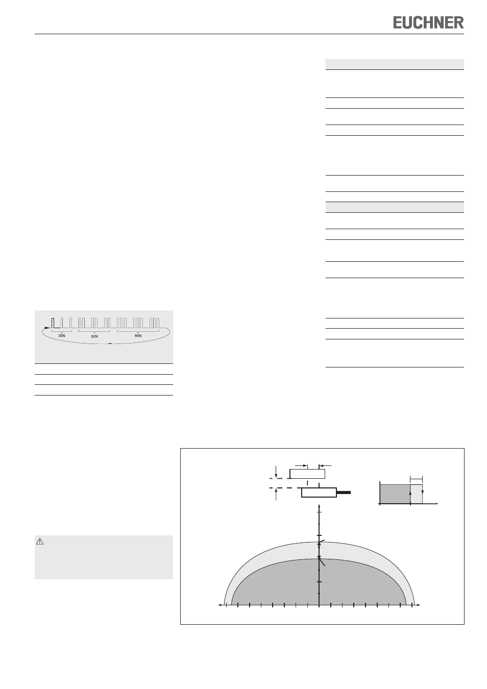
Center offset m [mm]
Distance s [mm]
OFF
ON
Hysteresis
Switch-on
distance
ON
OFF
Hysteresis
Distance s
S
a0
Output state
Switch-off
distance
OFF
Actuator
Read head
s
m
ON
Observe safe switch-off
distance s
ar
= 20 mm on
internal component failure.
Safety outputs are safely
switched off.
Typical operating distance
With evaluation unit CES-AZ-...B
Figure 2: Typical operating distance
Technical data
Parameter
Value
Material
- Housing
- Read head CES
- Solenoid
Aluminum
Plastic (PPS)
Galvanized steel
Installation position
Any
Degree of protection
according to IEC 60529
IP67
Ambient temperature
-25 ... +50 °C
Operating distance with
center offset m=0
Assured switch-off
distance S
ar
Switch-on distance typ.
Switching hysteresis
20 mm
2 mm
0.7 mm
Connection to evaluation unit
(plug connector X3)
Plug connector M8
(male socket, 3-pin)
Max. cable length
25 m
Solenoid
Adhesive force, adjustable
(due to pre-excitation)
30 N, 50 N (factory setting),
80 N
Locking force
500 N (not monitored)
Max. permissible center
offset between solenoid and
mating plate
± 2.5 mm
Operating voltage U
B
(plug connector X1)
DC 24 V +10%, -15%, reverse
polarity protected
Current consumption
at connection X1.2 (U
B
) at
U
CM
=24 V
U
CM
=0 V
at connection X1.1 (U
CM
)
100 mA
25 mA
10 mA
Duty cycle
100 %
Power consumption
approx. 2.8 W
Connection for operating
voltage U
B
Plug connector M8 (male
socket, 4-pin)
LED, yellow, integrated into
the plug (see circuit diagram)