Operating instructions read head cem-a-le05h-s2 – EUCHNER CEM-A-LE05H-S2 User Manual
Page 4
Operating Instructions Read Head CEM-A-LE05H-S2
EUCHNER GmbH + Co. KG Kohlhammerstraße 16 D-70771 Leinfelden-Echterdingen Tel. +49/711/75 97-0 Fax +49/711/75 33 16 www.euchner.de [email protected]
Correct use
Series CEM-A read heads are operated in combina-
tion with an evaluation unit in the system family
CES-AZ-...B. In this combination the read head CEM
is an interlock device with electromagnetic guard
locking without guard lock monitoring. The combi-
nation is not allowed to be used as guard locking
for the protection of personnel in accordance with
EN 1088.
In combination with a separating safety guard and
the machine control, this safety component prevents
dangerous machine movements from occurring
while the safety guard is open.
A stop command is triggered if the safety guard is
opened during the dangerous machine function.
For the control system, this means that
f
starting commands which cause hazardous situ-
ations must become active only when the safety
guard is in the protective position.
Before safety components are used, a risk as-
sessment must be performed on the machine in
accordance with
f
EN ISO 13849-1, Safety of machinery. Safety re-
lated parts of control systems. General principles
for design, Annex B
f
EN ISO 14121, Safety of machinery. Risk assess-
ment. Principles.
f
IEC 62061, Safety of machinery. Functional safety
of safety-related electrical, electronic and program-
mable electronic control systems.
Correct use includes compliance with the relevant
requirements for installation and operation, in
particular
f
EN ISO 13849-1, Safety of machinery. Safety re-
lated parts of control systems. General principles
for design
f
EN 1088, Safety of machinery. Interlocking
devices associated with guards. Principles for
design and selection
f
EN 60 204-1, Safety of machinery. Electrical equip-
ment of machines. General requirements.
The read head must be used only in conjunction with
the designated CEM actuator from EUCHNER. On
the use of different actuators or other connection
components, EUCHNER provides no warranty for
safe function.
The series CEM read head must be operated only
in combination with evaluation units in the system
family CES-AZ-...B. Please check this in the "Combi-
nation options" table in the manual of the evaluation
unit used.
Important:
f
The user is responsible for the integration of the
device in a safe overall system. For this purpose,
the overall system must be validated, e.g. in ac-
cordance with EN ISO 13849-2.
f
Correct use requires observing the permissible
operating parameters (see Technical data).
f
If a product data sheet is included with the
product, the information on the data sheet ap-
plies in case of discrepancies with the operating
instructions.
f
The PL that can be achieved depends on the
evaluation unit used.
Exclusion of liability and warranty
In case of failure to comply with the conditions for
correct use stated above, or if the safety instruc-
tions are not followed, or if any servicing is not
performed as required, liability will be excluded and
the warranty void.
Safety precautions
Safety components fulfill personal protection func-
tions. Incorrect installation or tampering can lead to
fatal injuries to personnel.
Check the safe function of the safety guard par-
ticularly
f
after any setup work
f
after the replacement of a system component
f
after an extended period without use
f
after every fault
Independent of these checks, the safe function of the
safety guard should be checked at suitable intervals
as part of the maintenance schedule.
Fatal injury due to incorrect connection or incor-
rect use.
f
Safety switches must not be bypassed (bridg-
ing of contacts), turned away, removed or
otherwise rendered ineffective. On this topic
pay attention in particular to the measures
for reducing the possibility of bypassing from
EN 1088:1995+A2:2008, Section 5.7.
The device may be installed and put into opera-
tion only by authorized experts
f
who are familiar with the correct handling of
safety components
f
who are familiar with the applicable EMC
regulations
f
who are familiar with the applicable regula-
tions on health and safety and accident
prevention
f
who have read and understood the operating
instructions and the system manual.
The switching operation must only be triggered
by actuators specifically provided for this pur-
pose (see ordering table) which are positively
connected to the safety guard.
Function
The CEM read head behaves like a CES read head
(see manual of the evaluation unit used). As soon as
the actuator reaches the operating distance of the
read head, a signal is sent to the evaluation unit.
CEM read heads additionally feature a solenoid to
produce the adhesive force and the locking force.
The guard locking is not monitored.
In order to attain the adhesive force, the guard
locking solenoid is pre-excited. This provides this
read head with adhesive force even when guard
locking is inactive.
The adhesive force can be set in steps of 30 N, 50
N and 80 N with the aid of a programming adapter
(see section Setting adhesive force)
The guard locking is activated when, in addition
to operating voltage U
B
, the control voltage U
CM
is
present (open-circuit current principle).
The LED on plug connector X1 is lit when the sole-
noid is energized.
Mounting
The read head must not be opened.
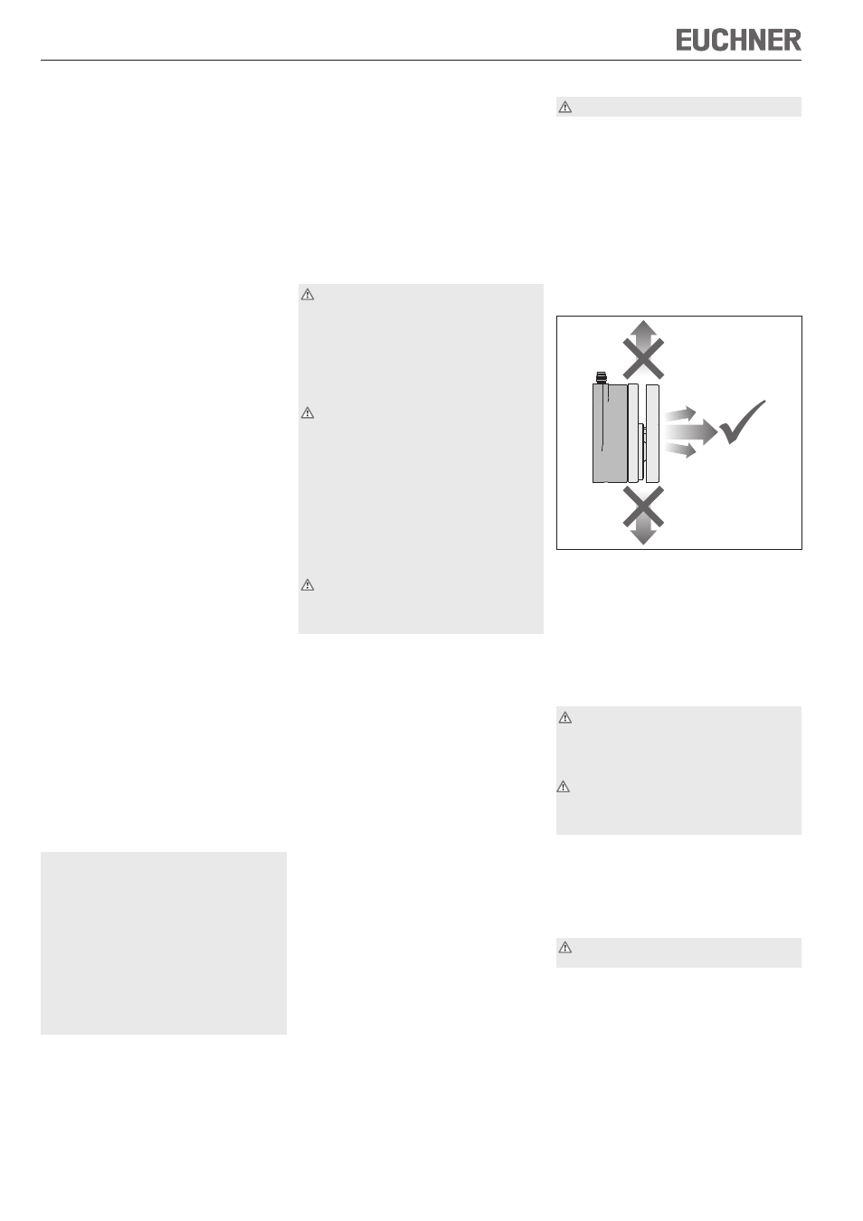
Install read head and actuator so that
f
when the safety door is opened, the actuator is
moved away from the read head toward the front
(see Figure 1 Approach direction).
f
access to it is difficult for operating personnel
when the safety guard is open
f
it is possible to check and replace the read
head.
f
Mount the read head positively.
f
Permanently connect the actuator to the safety
guard so that it cannot be detached, e.g. using
the enclosed non-removable screws, rivets or
welding.
Read head
Actuator
± 4°
Figure 1 Approach direction
Protection against environmental effects
Dirt on the surfaces of the read head and actuator
can reduce the adhesive force and the locking force.
Clean the surfaces at regular intervals.
Cover the read head, the actuator and the rating
plate during painting work!
Electrical connection
All the electrical connections must either be
isolated from the mains supply by a safety trans-
former according to IEC EN 61558-2-6 with limited
output voltage in the event of a fault, or by other
equivalent isolation measures.
If a common power supply is used, all the induc-
tive and capacitive loads (e.g. contactors) con-
nected to the power supply must be connected
to appropriate interference suppression units.
f
For terminal assignment see Figure 4.
f
For detailed information see the system manual
for the evaluation unit used.
Setup and functional check
Pay attention to the information in the system manual
for the evaluation unit used during setup.
Danger of fatal injuries as a result of faults in
installation and functional check.
f
Before carrying out the functional check,
make sure that there are no persons in the
danger area.
f
Observe the valid accident prevention regula-
tions.
Subject to technical modifications; no r
esponsibility is accepted for the accuracy of this information. © EUCHNER GmbH + Co. KG 110030-02-04/12 (translation of the original operating instructions)