Technical data, Ordering table – EUCHNER CES-A-UBA-01B (Multicode) User Manual
Page 18
Operating Instructions Safety System CES-A-UBA-01/CES-A-UBA-01B
18
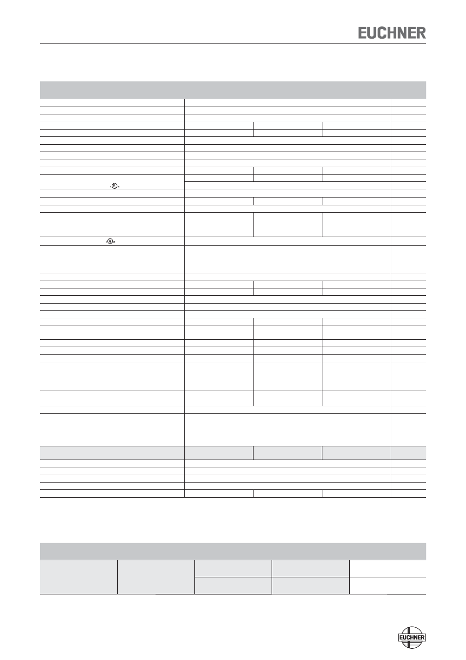
Technical Data
Parameter
Value
Unit
min.
typ.
max.
Housing material
Plastic PA6.6
Dimensions
114 x 99 x 22.5
mm
Weight
0.2
kg
Ambient temperature at U
B
= DC 24 V
-20
-
+55
°C
Atmospheric humidity, not condensing
-
-
80
%
Degree of protection
IP20
Degree of contamination
2
Installation
DIN rail 35 mm according to EN 60715
Number of read heads
1 read head per evaluation unit
Connection (plug-in screw terminals/coded)
0.14
-
2.5
mm²
Operating voltage U
B
(regulated, residual ripple < 5 %)
21
24
27
V DC
For the approval according to
the following applies
Operation only with UL Class 2 power supply, or equivalent measures
Current consumption (with relay energized)
150
mA
External fuse (operating voltage U
B
)
0.25
-
8
A
Safety contacts
2 (relays with internally monitored contacts)
Switching current (relay outputs)
mA
mA
- At switching voltage 21 ... 60 V
1
-
300
- At switching voltage 10 ... 30 V
10
-
6000
Switching load according to
Max. AC 30 V, class 2 / max. DC 60 V, class 2
External fuse (safety circuit) according to EN 60269-1
6 A gG or 6 A circuit breaker (characteristic B or C)
Utilization category to EN 60947-5-1
AC-12 60V 0.3A / DC-12 60V 0.3A
AC-12 30V 6A / DC-12 30V 6A
AC-14 30V 2A / DC-13 24V 3A
Classification according to EN 60947-5-3
PDF-M
Rated insulation voltage U
i
-
-
63
V
Rated impulse withstand voltage U
imp
-
-
1.5
kV
Rated conditional short-circuit current
100
A
Resilience to vibration
According to EN 60947-5-2
Mechanical operating cycles (relays)
10 x 10
6
Switching delay from state change
1)
-
-
180
ms
Time difference (between the switching points of the two
relays)
-
-
120
ms
Ready delay
2)
-
-
3
s
Dwell time
3)
0.5
-
-
s
Switching frequency max.
4)
-
-
1
Hz
Monitoring outputs (diagnostics ERR, door monitoring output
OUT, semiconductor output, p-switching)
5)
- Output voltage
0.8 x U
B
-
U
B
V DC
- Max. load
-
-
20
mA
Test input LOW
0
-
2
V DC
HIGH
15
-
U
B
EMC protection requirements
In acc. with EN 60947-5-3
LED displays
STATE
Green LED:
Normal operation
OUT
Yellow LED: Actuator detected
ERROR
Red LED:
- Test input activated
-
Internal
electronics
fault
-
EMC
interference
Reliability values according to EN ISO 13849-1
Switching current at 24 V DC
≤ 0.1 A
≤ 1 A
≤ 3 A
Category
3
PL
e
PFH
d
4.3 x 10
-8
Mission time
20
years
Number of switching cycles/year
760 000
153 000
34 600
1) Corresponds to the risk time according to EN 60947-5-3. This is the maximum switch-off delay for the safety outputs following removal of the actuator.
2) After the operating voltage is switched on, the relay outputs are switched off and the door monitoring contact is set LOW during the ready delay.
3) The dwell time of an actuator inside and outside the operating distance must be at least 0.5 s to ensure reliable detection of internal faults in the evaluation unit (self-monitoring).
4) If the current load is > 100 mA, a switching frequency of 0.1 Hz should not be exceeded as this will affect the mechanical life of the relay contacts.
5) Not short circuit-proof
Ordering table
Series
Category according to
EN ISO 13849-1
Typ. switch-on distance
[mm]
Number of read heads
Order no. / item
CES-A-UBA...
3
6
1
096960
CES-A-UBA-01
15
1
096961
CES-A-UBA-01B