Twin), Operating instructions safety switch stp-tw, Technical data – EUCHNER STP-TWxxx (Twin) User Manual
Page 6
Operating Instructions Safety Switch STP-TW...
(Twin)
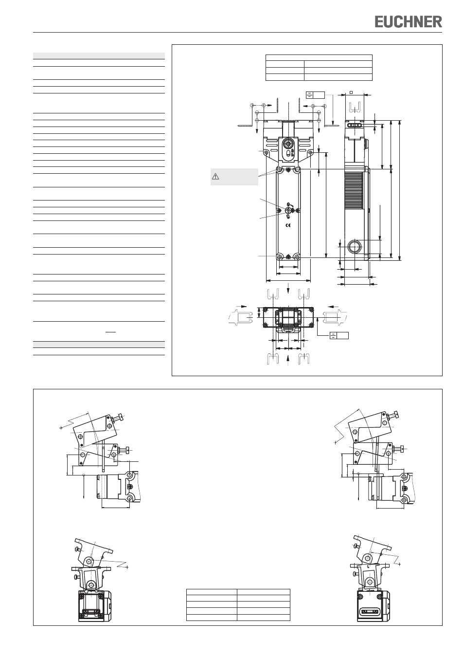
Figure 4: Dimension drawing STP-TW...
Figure 5: Min. door radii
Actuator type
Door radius min. [mm]
Actuator S-G...
300
Actuator S-W...
300
HINGED ACTUATOR S-OU...
200
HINGED ACTUATOR S-LR...
200
Hinged actuator S-OU-LN for
insertion funnel
Hinged actuator S-LR-LN for
insertion funnel
16
30
R >
200
35,5
4
28,5 +5
20
R>200
Hinged actuator S-OU-SN
Hinged actuator S-LR-SN
24,5 +5
12
26
35,5
R >
20
200
R>200
(F
Zh
=
F
max
) = 2,000 N
1,3
Technical Data
Parameters
Value
Housing material
Reinforced thermoplastic
Degree of protection
according to IEC 60529
IP67
Mech. Mechanical life
1x10
6
operating cycles
Ambient temperature
-20 ... +55°C
Degree of contamination
(external, according ?to
3 (industrial)
EN 60947-1)
Installation position
Any
Approach speed, max.
20 m/min
Extraction force (not locked)
30 N
Retention force
20 N
Actuating force, max.
35 N
Actuation frequency
7000 / h
Switching principle
Slow-action switching contact
Contact material
Silver alloy, gold flashed
Connection type
Screw terminal, M20x1.5
Conductor cross-section
(rigid/flexible)
0.34 ... 1.5 mm²
Operating voltage for
optional LED indicator
L024
24 V
Rated insulation voltage
U
i
= 250 V
Rated impulse withstand voltage U
imp
= 2.5 kV
Rated short-circuit current
100 A
Switching voltage, min.
12 V
at 10 mA
Utilization category
to EN 60947-5-1
AC-15 4 A 230 V / DC-13 4 A 24 V
Switching current, min., at 24 V 1 mA
Short circuit protection
(control circuit fuse)
4 A gG
according to IEC 60269-1
onv. thermal current Ith
4 A
Solenoid operating voltage/
solenoid power consumption
AC/DC 24 V (+10%/-15%) 8 W
Duty cycle
100 %
Locking force F
max
Straight actuator with bush
F
S
= 2,500 N
Bent actuator with bush
F
S
= 1500 N
Locking force F
Zh
in accordance with
test principles GS-ET-19
Reliability figures according to EN ISO 13849-1
B
10d
4.5 x 10
6
0,3
v
h
h
v
30
<40>
27
171
<72>
20
20
16
4
4
0,3
<74>
<80>
<42>
144
30
M20x1,5 (3x)
22
16
<39>
<228>
4
∅ 5.3 (2x)
for M5x35 mm
ISO 1207/ISO 4762
Mechanical
release
Locking screw
Necessary minimum travel + permissible overtravel
Approach direction
Actuator
S standard
Horizontal (h)
24,5 + 5
Vertical (v)
24,5 + 5
∅ 5.3 (2x)
for M5x35 mm
ISO 1207/ISO 4762
Do not use these
mounting holes!