Make connections and install the new backplane, N o t e – ETC Sensor+ Touring Rack CEM+ to CEM3 Retrofit User Manual
Page 16
14
CEM3 Sensor Touring Rack Retrofit Manual
Make Connections and Install the New Backplane
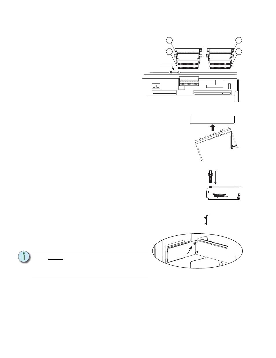
Step 1:
Install the dimmer output
ribbon cables/transition
cards. Open the black
retaining tabs for each
connector until they are at a
45° angle to the backplane.
Press the transition cards
into their respective
locations until the tabs lock
in place at a 90° angle to the
backplane.
Note: The order/layout for
the cables is not the same
as on the old backplane
(see illustration). Make sure the proper side is facing up on each connector
and that each connector is fully seated.
Step 2:
Bend one arm of the backplane metal in towards
the opposite arm (about 30 deg). Bend the metal
as little as possible to get it inside the rack.
Step 3:
Insert the backplane metal at an angle. Then
straighten it once it is past the face of the rack.
Push it into the rack far enough that it stays in
place, but leave yourself some room to make the
power and data connections.
Step 4:
Connect the power connector to the backplane
power header. Note the pin shapes for proper orientation.
It will only fit one way.
Step 5:
Now push the backplane completely into the rack. Be
careful of the power connection you just made. Make sure
that the wiring does not become stressed or pinched.
Step 6:
Insert tabs in the side of the rack.
Step 7:
With the tabs fully inserted in the sides of the rack, pull the
backplane towards the front of the rack to line up the
screw holes in the upper corners.
Step 8:
Install one screw with a sleeve
in the upper-corner of each side
of the backplane.
Step 9:
Plug the control input ribbon cable into the blue header on the backplane. The
connector is keyed - the ribbon cable will travel upwards from the backplane.
Step 10: Plug the 2' Ethernet cable into the RJ45 connector on the rear of the backplane.
N o t e :
You cannot use the old screws
without the additional shoulder-
sleeve as they will block the
CEM3 from being fully inserted.
CEM+ Ribbon Cable Layout
(1-24)
(73-96)
(49-72)
(25-48)
1
2
3
4
Control data
ribbon cable
header
Top View
Connect power
Screw with
sleeve