N o t e – ETC Sensor+ Touring Rack CEM+ to CEM3 Retrofit User Manual
Page 10
8
CEM3 Sensor Touring Rack Retrofit Manual
Step 6:
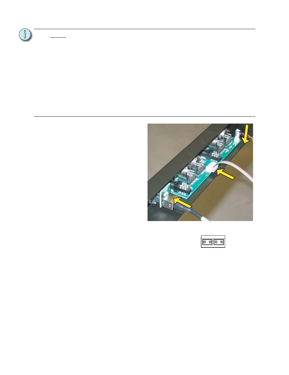
Connect the data cables
to the new control input
panel. The new multi-
colored ribbon cable and
ethernet cable are
included in your upgrade
kit.
a: Insert the Ethernet
cable in the RJ45 jack
on the rear of the
control input panel.
b: Connect the new
control data ribbon
cable connector (the
connector is keyed - the
ribbon cable will travel
up from the panel) in
the new control input
panel ribbon cable
header. Both ends of the control data ribbon cable are the same.
c: Connect the beacon connector (red and black wire)
to either the first or last pair of the beacon header
(shown here). SP96 and “Double Small” racks will
use both pairs.
d: For SP96 and “double small” racks, there is a second fan indicator LED on the
control panel. Connect the second fan indicator wire to the indicator on the right
side (from the front) of the control panel.
Step 7:
Feed the cables into the rack through the input panel opening and reinstall the
breaker with the two screws removed earlier. Be sure to note the proper on/off
orientation of the breaker to the panel labeling (The new panel and the old
panel are the same).
Step 8:
Install the new control input panel in the rack. Leave the screw on each end of
N o t e :
Early model CEM touring racks were discreetly wired and did not have a PCB
containing DMX in, thru, and termination.
If you have one of these racks, after removing the control input panel, you will
need to disconnect two (SP48) or three (SP96) red and black twisted pairs from
the backplane. One runs to the old control input panel and may be discarded after
removal. The other runs from pins 5 and 7 on the old backplane beacon connector
to the front beacon (dimmer module side of the rack). On SP96 and “double small”
racks there will be two pairs of wires running from these pins. This pair must be
disconnected from the old backplane beacon connector and connected to the new
control input panel. This will require extending the pair (or pairs on 96 racks) using
an additional red/black twisted pair length (7050B7016) and two butt splice
connectors (J4163) which are included in the kit (two kits are included for 96
racks).
Splice the twisted pair length to the old front beacon wire (red-to-red, black-to-
black) using the butt splices and connect the MAS-CON connector to the control
input panel in the location shown below.
Conn
ect
C
onn
ec
t
Conn
ect
Use either pair