Power termination – ETC Sensor+ Touring Rack CEM+ to CEM3 Retrofit User Manual
Page 12
10
CEM3 Sensor Touring Rack Retrofit Manual
Power Termination
Step 1:
Follow the path of the existing J1 power wiring and clip the first wire-tie holding
the J1 power connector in place. This will make it easier to move the harness
while you work.
Step 2:
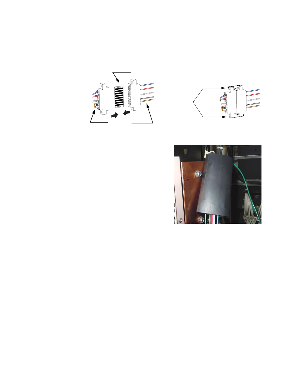
Install the power adapter harness to the edge connector (straight thru PCB) to
the old power connector (match the wire colors)
.
Step 3:
Secure the power connectors together with the provided 4" wire-ties. Clip the
wire tie ends for neatness.
Step 4:
Slide the heat shrink over the two
mated connectors. Make sure the
green ground wire comes out of the
heat shrink on the appropriate side.
Step 5:
Heat the heat shrink using a heat
gun until it has constricted the
mated connectors.
Step 6:
While the heat shrink is still warm,
fold in the ends and secure with tie
wraps at each end. This will keep
debris from falling into the
connection.
Step 7:
In line with the intended backplane
position and past the back of the
sheet metal, mount a sticky-back
tie wrap mount.
Step 8:
Use that tie wrap mount to loosely secure the power harness to the side of the
rack. Leave the tie wrap loose enough so the power harness can slide backwards
when the backplane is installed.
Step 9:
Run the green grounding wire to any open terminal on a grounding bar (such as
an outlet panel or soccapex panel) making sure to dress the cable through any
existing wire clips in the rack.
Step 10: Secure the grounding wire to the ground terminal using an open ground wire
terminal.
Oh, I wish
I were an
Oscar Meyer® wi
ener...
Wire-tie the
connectors
together
The PCB is the same on
both sides, top and bottom.
Match the
wire colors