Data cabling preparation, N o t e – ETC Sensor+ Touring Rack CEM+ to CEM3 Retrofit User Manual
Page 13
2
The Retrofit
11
Data Cabling Preparation
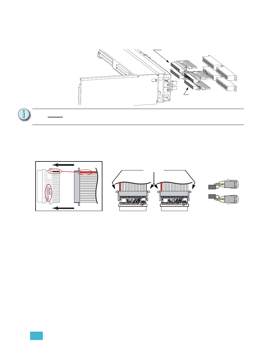
Step 1:
Identify the different dimmer output ribbon cable transition cards. An SP48 will
only use a single upper and lower card.
Step 2:
Mate the transition cards with the ribbon cable edge connectors as indicated
below. Secure the ribbon cable connectors to the transition cards with wire ties.
The tie wrap binding needs to be on the top for an Upper board and on the
bottom for a Lower board for adequate clearance. Clip wire tie ends for
neatness.
N o t e :
There are two different types. An “upper” card and a “lower” card. The transition
card is marked with both the type and which side should be up when installed.
1
3
4
2
This is an “Upper”
transition board
(7150B5007)
This is a “Lower”
transition board
(7150B5006)
Match
the red
wire to
pin-1
and be
sure the
proper
side is
up
Wire tie the
connectors
together
Position of the
tie wraps
On top for Upper
On bottom for Lower