ETC Sensor+ Touring Rack CEM+ to CEM3 Retrofit User Manual
Page 15
2
The Retrofit
13
Spider Board Retrofit (only SP96 Large or “Double Small”)
Sensor 96 dimmer touring racks have a “Spider board” installed, which assisted in phase
balancing. This functionality is now handled by CEM3 and the spider board must be
replaced with a new board for proper dimming functionality.
In a double small rack, it is best to access the spider board through the opened left side of
the rack.
In a large frame rack, it is recommended that you access the spider board through the
center column of dimmer modules or through the right side of the rack. When using the
center column, remove enough modules to give you adequate room to access the boards.
The following procedure illustrates the spider board replacement process.
To replace the spider board:
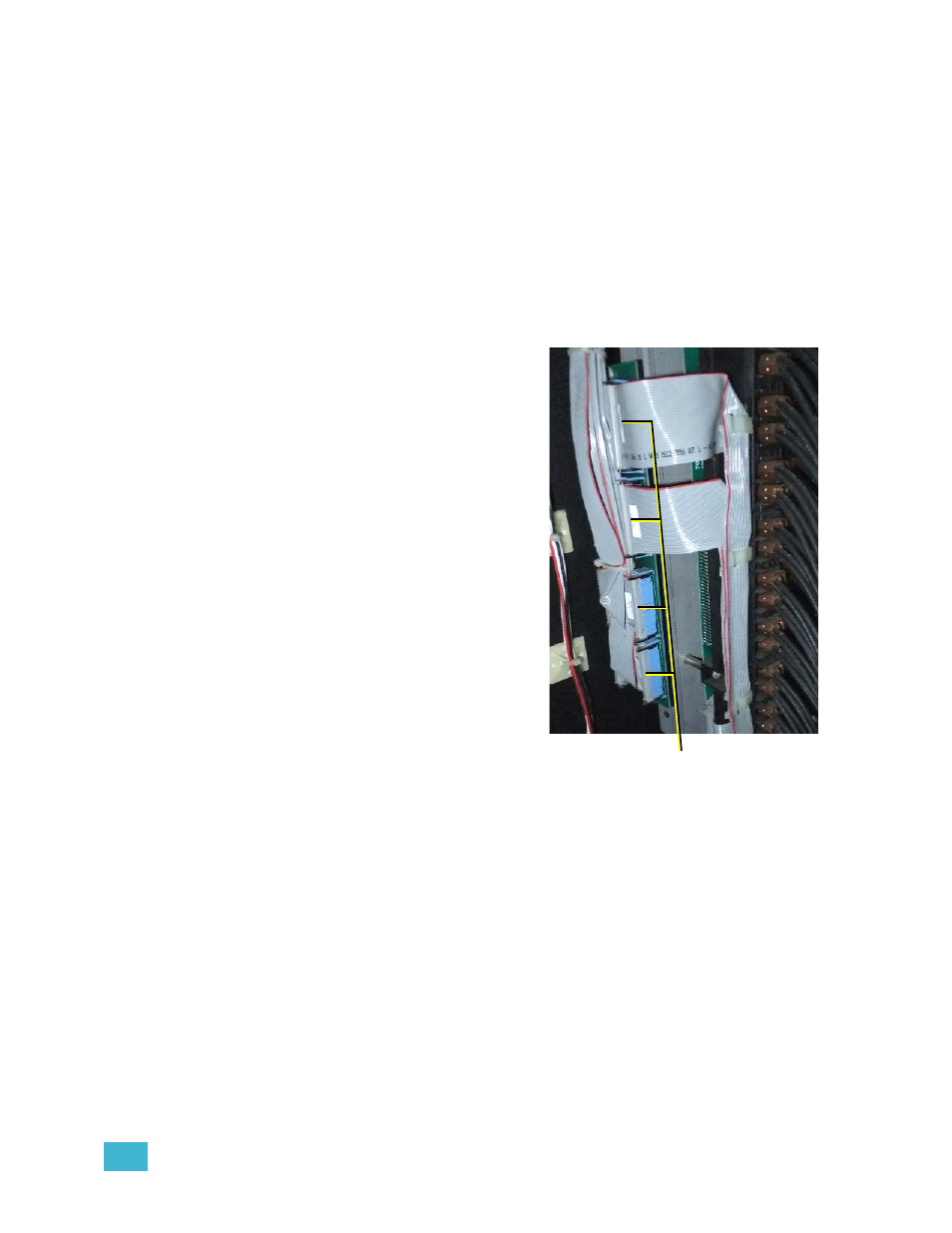
Step 1:
Disconnect the first column of
ribbon cables from the spider
board. This will give you
access to the three mounting
screws. The cables are clipped
and retained in such a way that
labelling them should be
unnecessary.
Step 2:
Remove the three screws that
secure the board to the rack
using a short phillips head
screwdriver. Be careful not to
drop the screws into the rack
as they will need to be
retrieved.
Step 3:
Disconnect the second row of
ribbon cables and remove the
board.
Step 4:
Twist the screws into the
screws holes in the new spider
board. The holes should be
small enough to hold the
screws.
Step 5:
Connect the second row of
ribbon cables removed in Step 3 to the new board.
Step 6:
Align the screws with the screw holes in the rack and tighten using a short phillips
head screwdriver.
Step 7:
Connect the remaining ribbon cables to the open connectors on the spider board.
A small inspection mirror may be useful for this.
Disconnect this row of ribbon cables first