The retrofit, Preparation, Remove the old – ETC Sensor+ CE Rack (ESR+) CEM+ to CEM3 Retrofit User Manual
Page 7
2
The Retrofit
5
S e c t i o n 2
The Retrofit
Preparation
Step 1:
www.etcconnect.com
).
Step 2:
Turn off main power to the rack(s). Before removing dimmer or control
modules for service, de-energise main feed to dimmer rack and follow
appropriate safety procedures for your region.
Step 3:
Remove the eight dimmer modules above the CEM+ (if retrofitting an ESR+48 or
36 rack, remove the eight modules below the CEM+ as well). Note and document
the modules’ order/positioning in the rack for proper insertion and configuration
later.
Step 4:
Use a digital voltmeter and VERIFY that power is off by checking voltages for
all combinations between the phase bars, neutral and earth.
Step 5:
Remove the CEM+ from the rack.
Remove the Old
Step 1:
Disconnect the DMX plug-in connectors and CAT5 cable from the backplane and
label them accordingly.
Step 2:
If fitted, label and disconnect the Panic In, Panic Out, External Beacon and
SmartLink wires from the screw terminal block of the CEM+ backplane.
N o t e :
If your backplane includes an IEC connector for the NEFM (Network Electronics
Filler Module) there are additional steps you will need to perform to transfer these
components to the new backplane. These steps are included throughout the
following procedure and are indicated by “(IEC ONLY)” at the start of the step.
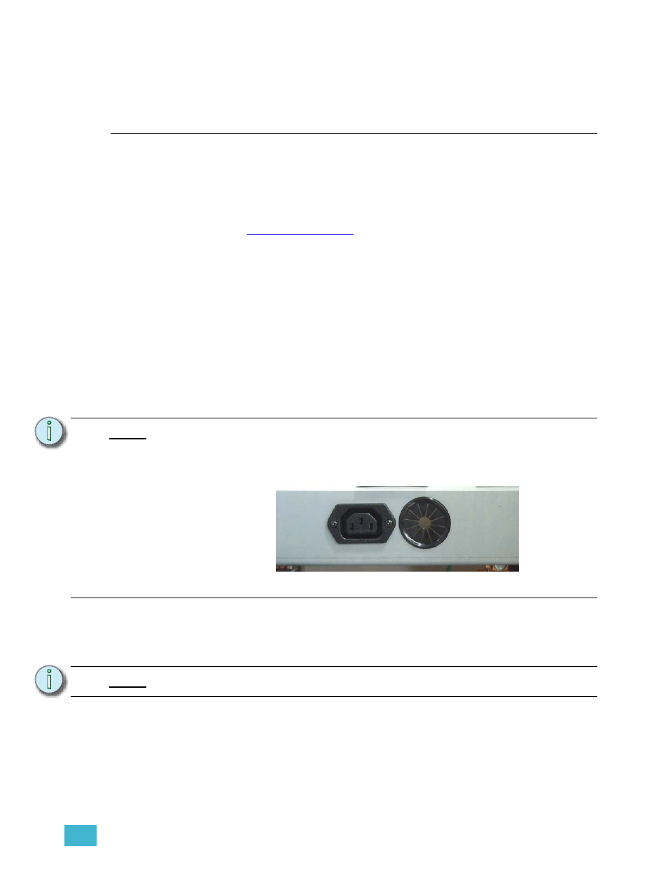
N o t e :
Sensor+ SmartLink stations are not compatible with Sensor3.
IEC Connector and grommet (below CEM+)