Change out the af cards (if present) – ETC Sensor+ CE Rack (ESR+) CEM+ to CEM3 Retrofit User Manual
Page 14
12
CEM3 Sensor+ ESR+ Rack Retrofit Manual
“On” position = switch pushed to the top
d: Check to see that the “Emergency Contact” switch is set to the appropriate
position.
• If your system has no panic circuit, the switch should be set to the middle
position, “DISABLED”.
• If your panic circuit includes a Normally Open contact closure, the switch
should be set to the top position (NO).
• If your panic circuit includes a Normally Closed contact closure, the switch
should be set to the bottom position (NC).
Change out the AF Cards (if present)
If your rack supports Advanced Features (AF)
you may need to replace the AF cards as well.
CEM3 only supports use of the newer-style AF
cards which have eight address witches (instead
of four) as well as two LEDs (shown at right). If
your cards do not have these features, you must
order new cards for your retrofit.
AF cards are located on the right side of the
dimmer module slot between the copper neutral
busses and the dimming circuitry cards.
To function with CEM3, AF cards must be the
new type with two LEDs and eight switches.
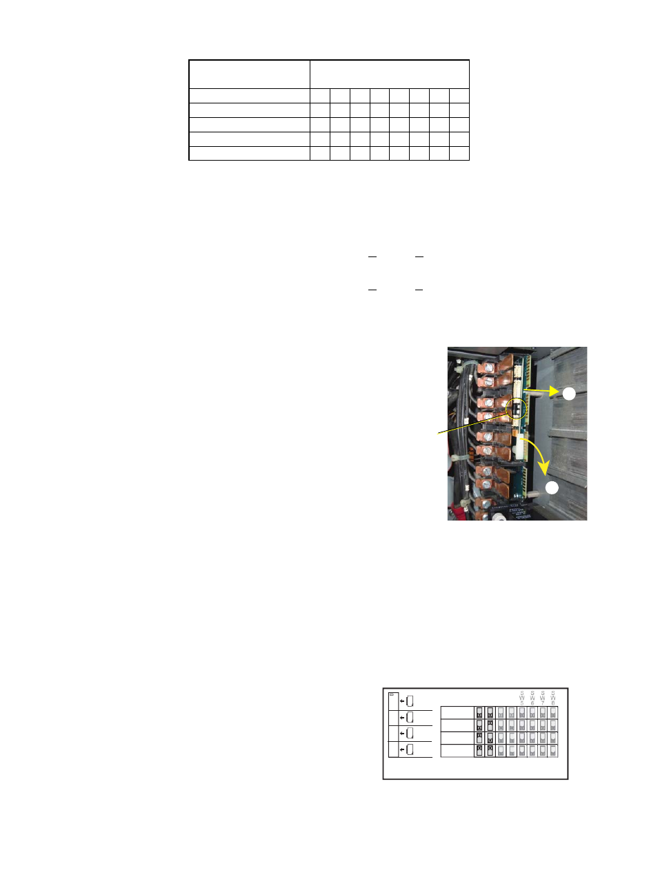
To replace the AF cards:
Step 1:
Remove the old AF cards by flipping
the white retainer tab on the cards into the down position
Step 2:
Pull the old cards out of the slots.
Step 3:
Set the DIP switches on the new cards according to the chart below. Only the first
two DIP switches are used.
Step 4:
Slide the new AF cards completely into the vacant slots starting with card #1 in
the top. The number of cards depends on rack size.
Step 5:
Flip the white tab up to lock the new card in place.
ESR3-36AFN
On
On On On
ESR3-48
On
ESR3-48N
On On
ESR3-48AF
On
On
ESR3-48 AFN
On
On On
DIP switch Number
Rack Model
1
2
3
4
5
6
7
8
Flip tab down, pull card out
1
2
LEDs found
on newer
cards
AF Card Addressing
Card 1
Card 2
Card 3
Card 4
S
W
1
S
W
2
S
W
3
S
W
4
1
ESR3-12
ESR3-24
ESR3-48
2
3
4
Sensor+
Off = Switch in down position
ESR3-36