ETC Sensor+ CE Rack (ESR+) CEM+ to CEM3 Retrofit User Manual
Page 12
10
CEM3 Sensor+ ESR+ Rack Retrofit Manual
.
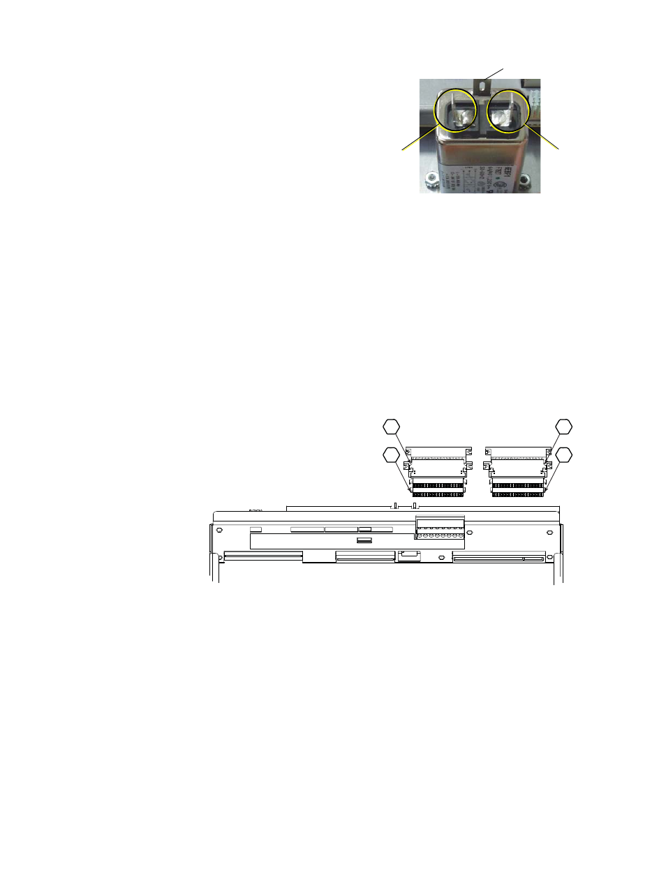
Step 5:
(IEC Only) connect the
brown and blue wires to the
rear of the IEC connector in
the NEFM slot. Connections
should be made according to
the image at right.
Step 6:
Make the power and data connections on the backplane.
a: Install the dimmer output ribbon cables. Open the black retaining tabs for each
connector until they are at a 45° angle to the backplane. Press the connectors
into their respective locations until the tabs lock in place at a 90° angle to the
backplane. Make sure the proper side is facing up on each connector and
that each connector is fully seated.
b: Install the power harness (Look at the pin shapes for proper orientation. It will
only fit one way.)
c: Install the DMX connections. The wires travel out of the top on both styles of
connectors.
d: Install the 3-pin beacon connector. The wires travel out of the top of the
connector.
e: Connect the CAT5 Ethernet cable to the RJ-45 connector on the CEM3
backplane. (Not shown in the drawing below for clarity.).
Step 7:
Push the backplane completely into place in the rack. Be careful not to disrupt
the power and data connections you just made. Make sure none of the wiring
becomes stressed or pinched.
Step 8:
Insert the backplane tabs in the side of the rack.
Connect
brown wire
here
Connect
blue wire
here
Earth wire
CEM+ Ribbon Cable Layout
(1-24)
(73-96)
(49-72)
(25-48)
1
2
3
4