Backplane settings, N o t e – ETC Sensor+ CE Rack (ESR+) CEM+ to CEM3 Retrofit User Manual
Page 13
2
The Retrofit
11
Step 9:
With the tabs fully inserted in the
sides of the rack, pull the
backplane towards the front of
the rack to line up the screw
holes in the upper side corners
to line up.
Step 10: Install one screw with a sleeve in
the upper-corner (for single-
height backplanes) or the middle
of the rear edge (for dual-height backplanes) of each side of the backplane.
Step 11: Connect Panic In, Panic Out and External Beacon to the CEM3 screw terminal
block.
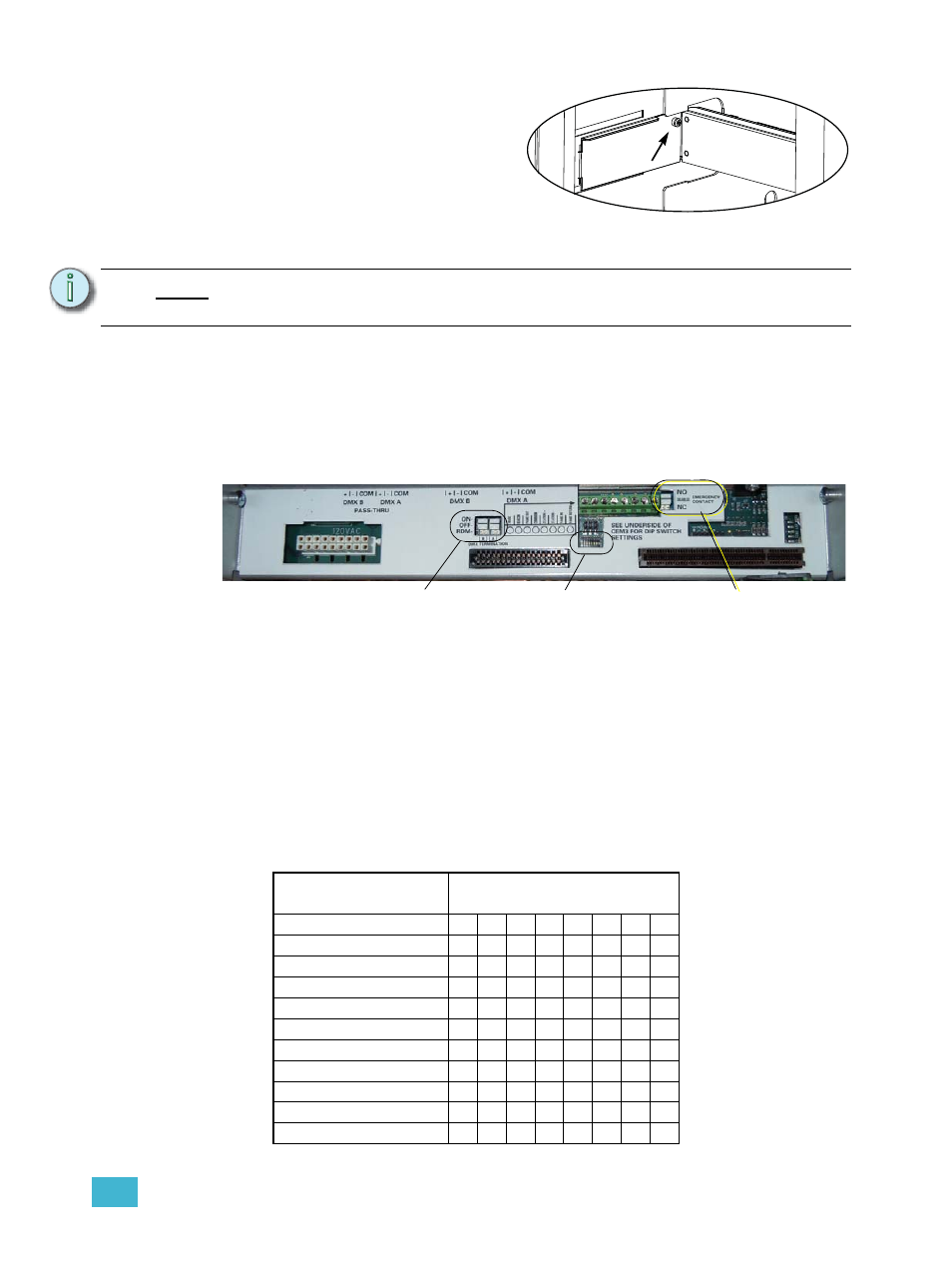
Backplane Settings
Upgrade kit backplanes ship from the factory with all DIP switches in the off (down) position.
You will have to set the DIP switches on the new backplane to match your rack. You will
also have to verify the termination switch settings.
a: Set both termination switches to “Off” (middle position) for all racks except the
last rack in your system.
b: Set the termination switches for the last rack in the system to “ON” (top
position).
c: Using a precision screwdriver, set the DIP switches to match your rack type
according to:
• number of modules (12, 24, 36, or 48)
• whether the rack has Advanced Features (AF)
• whether the rack is a neutral disconnect rack
Use the following chart to determine your required DIP switch settings:
N o t e :
You cannot use the screws without the additional shoulder-sleeve as they will
block the CEM3 from being fully inserted.
DIP switch Number
Rack Model
1
2
3
4
5
6
7
8
ESR3-12
On
On
ESR3-12N
On On
On
ESR3-12AF
On
On
On
ESR3-12AFN
On
On On
On
ESR3-24
On
On
ESR3-24N
On On
On
ESR3-24AF
On
On
On
ESR3-24AFN
On
On On
On
ESR3-36
On
On
ESR3-36N
On On On
ESR3-36AF
On
On
On
Screw with
sleeve
Single height backplane shown
Set termination to “Off”
(middle position)
Set DIP switches
Emergency Contact
(Panic) switch