Enerpac VE-Series User Manual
Page 2
2
CAUTION: Keep hydraulic equipment away from
flames and heat. Excessive heat will soften packings
and seals, resulting in fluid leaks. Heat also weakens
hose materials and packings. For optimum performance do
not expose equipment to temperatures of 65°C [150°F] or
higher. Protect hoses and cylinders from weld spatter.
DANGER: Do not handle pressurized hoses. Escaping
oil under pressure can penetrate the skin, causing
serious injury. If oil is injected under the skin, see a doctor
immediately.
WARNING: Only use hydraulic cylinders in a coupled
system. Never use a cylinder with unconnected
couplers. If the cylinder becomes extremely
overloaded, components can fail catastrophically causing
severe personal injury.
WARNING: BE SURE SETUP IS STABLE BEFORE
LIFTING LOAD. Cylinders should be placed on a flat
surface that can support the load. Where applicable,
use a cylinder base for added stability. Do not weld or otherwise
modify the cylinder to attach a base or other support.
Avoid situations where loads are not directly centered
on the cylinder plunger. Off-center loads produce
considerable strain on cylinders and plungers. In
addition, the load may slip or fall, causing potentially
dangerous results.
Distribute the load evenly across the entire saddle
surface. Always use a saddle to protect the plunger.
IMPORTANT: Hydraulic equipment must only be
serviced by a qualified hydraulic technician. For repair
service, contact the Authorized ENERPAC Service
Center in your area. To protect your warranty, use only
ENERPAC oil.
WARNING: Immediately replace worn or damaged
parts by genuine ENERPAC parts. Standard grade
parts will break causing personal injury and property
damage. ENERPAC parts are designed to fit properly and
withstand high loads.
3.0 INTRODUCTION
The Enerpac Modular Valves provide many different
options to allow control of multi-cylinder or complex control
of 10,000 psi systems. Traditional 10,000 psi valves, such
as the “VS” and “VM” Series, feature a tandem center
configuration, which prevents their use in most multiple
cylinder circuits.
The “VE” Series of Modular Valves are available with many
different center configurations, making them ideal for
complex, multi-cylinder applications. In addition, the “VE”
Series also features manifold options and “stackable”
accessory valves for even more flexibility in circuit and
mounting configurations. The “VE” Series Valves are
available with different solenoid voltages, 115 VAC and 24
VDC being the most popular.
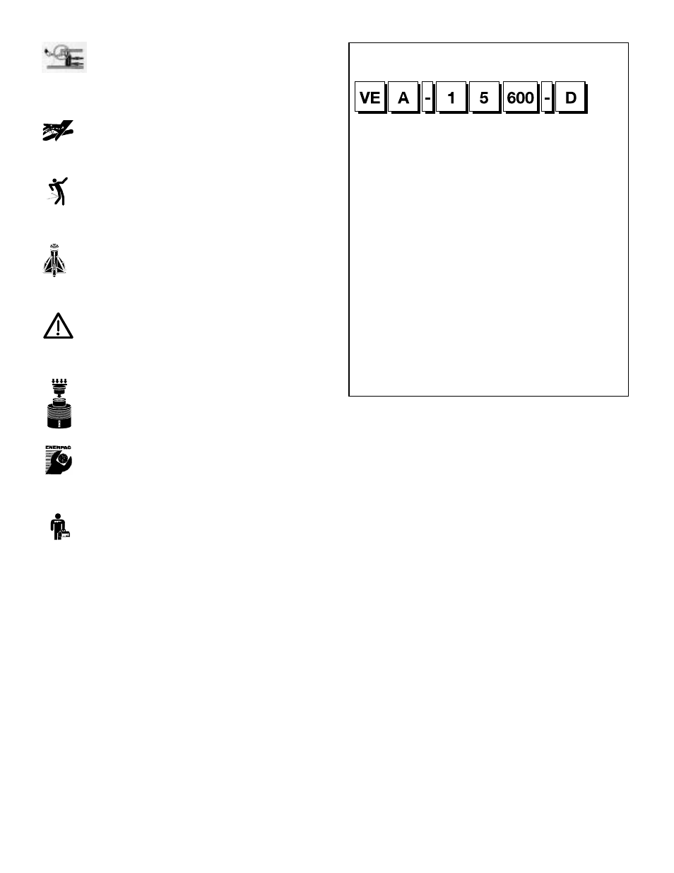
Figure 1, Modular Valve Model Number Matrix
4.0 GENERAL INFORMATION
The Enerpac “VE” Series valves are modular in design.
They can be used in simple applications in their least
complex format, or be equipped with optional accessories
to operate complex, multi-cylinder systems.
The “VE” Series valve include the following design features:
• 10,000 psi operating pressure
• Optional load-holding capability
• Optional integral relief valve for system pressure control
• Manual over-ride capability
• Pump mount or remote mount manifold options
• Multiple center configurations
• Available 2-position or 3-position configurations.
Due to the flexibility in models, the “VE” Series of valves that
are purchased as stand alone models do not include
electrical controls. The user is responsible for providing
electrical control capability, depending on the application.
When purchased on one of the PER/WER-1000 Series
Submerged Pumps, the valve is supplied with a pendent
control.
5.0 ASSEMBLY
When purchased, the “VE” Series valves may be ordered
with all accessories installed by the factory. When ordered
this way, whether pump mounted or remote mounted, the
valve is assembled and ready to mount on a pump or
1
Solenoid
Operated
Valve
2
Valve
Flow
Path
3
Flow
Capacity
4
Voltage
5
Accessory
Valves
6
Manifold
1 Product Type
VE = Solenoid Operated Valve
2 Valve Code
A = 4/3 Open Center
B = 4/3 Closed Center
C = 4/3 Tandem Center
D = 4/3 Float Center
E = 4/2 Crossover Offset
F
= 3/3 Tandem Center
G = 3/3 Closed Center
H = 2/2 Normally Closed
K = 2/2 Normally Open
M = 4/2 Float Offset
P = 3/2 Normally Open
3 Flow Capacity
1
= 4 gallons per minute
4 Voltage
1
= 24 VDC
2
= 220/240 V, 1 ph, 50 Hz
5
= 115 V, 1 ph, 60 Hz
6
= 230 V, 1 ph, 60 Hz
5 Accessory Valves
000 = No accessory valves
100 = Relief Valve only
150 = Relief Valve and 3-way pilot
operated check valve
Only for VEF/VEG
160 = Relief Valve and 4-way pilot
operated check valve
Only for VEA/VEB/VEC/VED
500 = 3-way pilot operated
check valve
Only for VEF/VEG
600 = 4-way pilot operated
check valve
Only for VEA/VEB/VEC/VED
6 Manifold
A = No manifold
B = Remote Mounted
D = Pump Mounted*
* Only for valve code:
VEA/VEC/VEE/VEF/VEK/VEP
Custom build your Modular Valves
▼
This is how a Modular Valve Model Number is built up:
®